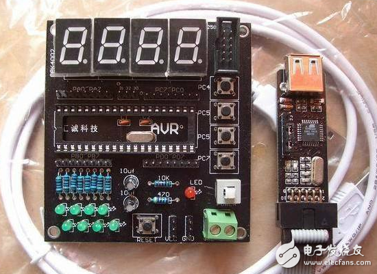
This article introduces the program implementation of the two AVR microcontroller 8-bit digital tube display.
AVR microcontroller 595 drives the display circuit of 8-bit digital tube to realize the main program code#include >
#include //Time delay function header file in GCC
#include "hc595.h"
/ / / / / / / / / / / / /
Unsigned char Led_Disbuf[10]={0xC0,0xF9,0xA4,0xB0,0x99,0x92,0x82,0xF8,0x80,0x90}; //common anode
Unsigned char ComBuf[8] = {0x01,0x02,0x04,0x08,0x10,0x20,0x40,0x80};
/ / Function statement
Extern void Delayus(unsigned int lus); //us delay function
Extern void Delayms(unsigned int lms); //ms delay function
Int main(void) //The main file in GCC must be a function that returns the integer value, no parameters
{
Unsigned char i;
PORTB = 0xff; //PORTB outputs low level, causing the LED to go out
DDRB = 0xFF; //Configure port PB as all output ports
HC595_port_init();
While(1)
{
For(i = 0; i < 8;i++)
{
PORTB = Led_Disbuf; //Send segment code
HC595_Send_Data(ComBuf); // strobe bit selection port
Delayus(70); //delay
HC595_Send_Data(0x00); //bit strobe is off
}
}
}
//us level delay function
Void Delayus(unsigned int lus)
{
While(lus--)
{
_delay_loop_2(4); //_delay_loop_2(1) is delayed by 4 clock cycles, parameter is 4 and delay is 16
// clock cycle, this experiment uses 16M crystal, then 16 clock cycles is 16/16=1us
}
}
//ms level delay function
Void Delayms(unsigned int lms)
{
While(lms--)
{
Delayus(1000); //delay 1ms
}
}

Below is the .h file for modular programming in this example.
/*****************************
74hc595.h
***********************************/
/*74hc595 pin connection to the microcontroller
/MR (10-pin) VCC Low-point normally clears the data of the shift register. Usually connect it to Vcc
/OE (13-pin) Output is disabled when PG4 is high (high-impedance state).
If the pin of the microcontroller is not tight, use a pin to control it.
It is easy to produce flicker and extinguishing effects. It saves time and effort compared to shifting control through the data terminal.
ST_CP (12-pin) The data of the shift register enters the data storage register on the rising edge of PG1.
The storage register data does not change on the falling edge. Usually set RCK low,
When the shift is over, a positive pulse is generated at the RCK terminal (5V, more than a few tens of nanoseconds).
The microseconds are usually selected to update the display data.
SH_CP (11-pin) Data shift of the data register at the rising edge of PG0. QA-->QB-->QC-->. . . -->QH;
The falling edge shift register data does not change. (Pulse width: 5V, more than tens of nanoseconds.)
Usually choose microseconds)
DS(14) PG2 serial data input.
*/
#ifndef __HC595_H__
#define __HC595_H__
#include //io port register configuration file, must contain
#include //Time delay function header file in GCC
#define HC595_latch (1 << PG1) //The rising edge data is driven into the 8-bit latch, and the falling edge latch data is unchanged.
#define HC595_sclk (1 << PG0) //Rising edge data shift, falling edge data unchanged
#define HC595_oe (1 << PG4) //Low level, 8-bit data latch output, high level output high configuration
#define HC595_data (1 << PG2) // Serial data input
#define SET_HC595_latch (PORTG | = (1 << PG1))
#define CLR_HC595_latch (PORTG &= ~(1 << PG1))
#define SET_HC595_sclk (PORTG |= (1 << PG0))
#define CLR_HC595_sclk (PORTG &= ~(1 << PG0))
#define SET_HC595_data (PORTG |= (1 << PG2))
#define CLR_HC595_data (PORTG &= ~(1 << PG2))
#define SET_HC595_oe (PORTG |= (1 << PG4))
#define CLR_HC595_oe (PORTG &= ~(1 << PG4))
Void HC595_port_init(void); //595 port initialization
Void HC595_Send_Data(unsigned char byte); //send one byte
Void HC595_Output_Data(unsigned char data); //send string
#endif
At the same time, we will put the 74HC595 related function definition part in the 74HC595.c file, as follows
/********************************
74hc595.c
**************************************/
#include "hc595.h"
//595 port initialization
Void HC595_port_init(void)
{
PORTG = 0x00;
DDRG | = (1 << PG0) | (1 << PG1) | (1 << PG2) | (1 << PG4);
}
/ / Send a byte
Void HC595_Send_Data(unsigned char byte)
{
Unsigned char i;
//CLR_HC595_latch;
For(i = 0;i < 8;i++)
{
If(byte & 0x80)
{
SET_HC595_data;
}
Else
{
CLR_HC595_data;
}
Byte <<=1;
SET_HC595_sclk; //rising edge data shift
CLR_HC595_sclk;
}
SET_HC595_latch;
CLR_HC595_latch;
}
/ / Send string
Void HC595_Output_Data(unsigned char data)
{
CLR_HC595_latch; // falling edge latch data unchanged
HC595_Send_Data(data);
SET_HC595_latch; // rising edge data into 8-bit latch
}
Capacitor for Electric Furnace
Capacitor For Electric Furnace, commonly referred to as capacitors, are capacitors, expressed in the letter C.Definition 1: a capacitor, as the name implies, is a "charging vessel", a device that holds charge.Capacitor.Capacitors are one of the most widely used electronic components in electronic equipment. They are widely used in the fields of interleaving, coupling, bypass, filtering, tuning circuit, energy conversion and control.Definition 2: a capacitor consisting of any two conductors (including wires) that are insulated from each other and are very close together.
Components Capacitors,High Voltage Capacitors,Low Frequency Capacitor,Water Pump Capacitor,Capacitor for Electric Furnace
YANGZHOU POSITIONING TECH CO., LTD. , https://www.pst-thyristor.com