For an RF test cable assembly, application engineers are not only concerned with their factory specifications, but also more concerned about their service life. The life of an RF cable assembly depends on three factors: the bending resistance of the cable itself, the good connection between the cable and the connector, its resistance to bending, and the life of the connector. For the first two factors, . . .
For an RF test cable assembly, application engineers are not only concerned with their factory specifications, but also more concerned about their service life.
The life of an RF cable assembly depends on three factors: the bending resistance of the cable itself, the good connection between the cable and the connector, its resistance to bending, and the life of the connector. For the first two factors, it can be ensured by the fixture or the operator's action; for the life of the joint, it can only be guaranteed by the quality of the joint itself and the assembly process.
Taking the N-type connector as an example, in the international standards of RF connectors, such as the US military standard MIL-C-39012 and the International Electrotechnical Commission IEC 60169-16, the insertion and extraction life of the N-type (copper) connector is 500. Times.
It is described as follows: under the condition of 12 laps/minute, the minimum insertion and removal is 500 times, and the connector should meet the matching requirements. In IEC 60169-16, the minimum insertion and removal life is 500 times under a torque of 0.7-1.1 Nm.
In the communication with the users of the RF test cable, we can often hear such a voice: 500 times? Too few, we have to use at least thousands of times because we do not know the specific meaning of the various application conditions of the connector and the indicators specified in the standard. Careful analysis of the additional conditions of the indicators specified in the standard and combined with the practical experience can be used to define the life of the RF connector to the following conclusions:
The life of 1.500 times is an indicator under the condition of the specified torque of the N-type connector (0.7-1.1 Nm). To achieve this torque, a special torque wrench is required, which cannot be achieved by ordinary people. I have done a test for the N-type connector: when it feels that the hand has been tightened, it can be tightened nearly half a turn with a standard torque wrench (Suhner P/N 74 Z-0-0-193).
2. The meaning of the so-called 500 lifespan is that all electrical indicators are guaranteed to be within the specified range of the factory specifications when inserted and removed 500 times according to the specified torque. Take the test cable produced by BXT as an example (Nm-Nm, 1 meter long, BXT P/N RG223-03-03-1000A). Its factory specification is insertion loss 0.84~1.4dB/dc-3GHz; standing wave ratio is 1.15. ~1.25@dc-3GHz. After 500 times of plugging and unplugging, the above indicators are still guaranteed.
3. Except for precision metering and calibration tests, expensive standard torque wrenches are rarely used on the production line to disassemble the RF connectors. Therefore, in actual use, the torque of the RF connector is much smaller than the specified value. At the same time, the human-tightened connector can fully meet the requirements of the indicator. This creates conditions for extending the life of the connector.
As a provider of test cable assemblies, BXT does not only want to reduce the torque to extend the life of the RF connector, but to ensure a long enough life from the quality of the connector itself.
So, how long is the life of an RF connector? In order to obtain a relatively accurate data, the author conducted a plug-and-pull life test of the RF connector.
Plug and pull life test method for RF connectorThe test object is a RG223 test cable assembly (BXT P/N: RG223-03-03-1000A) with a length of 1 m and a Nm end. The screw sleeve and outer conductor of the tested Nm joint are made of copper-plated ternary alloy. Material, the inner conductor is made of gold-plated copper. The test was carried out under the following conditions:
1. Test the Nm interface at one end, dock with an Nf connector, and connect and disassemble with a wrench. In order to ensure the accuracy, the Nf joint of stainless steel is used. In general, the life of the connector of stainless steel is 1000 times, which is twice as high as that of copper.
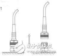
2. Each insertion and removal is a cycle (Fig. 1). The insertion loss of the cable assembly and the standing wave of the interface of the tested end are measured after every 100 insertions and removals, and the value at the 2.2 GHz frequency point is recorded. The test was carried out 2,400 times.

Figure 1. Life test method for RF connectors
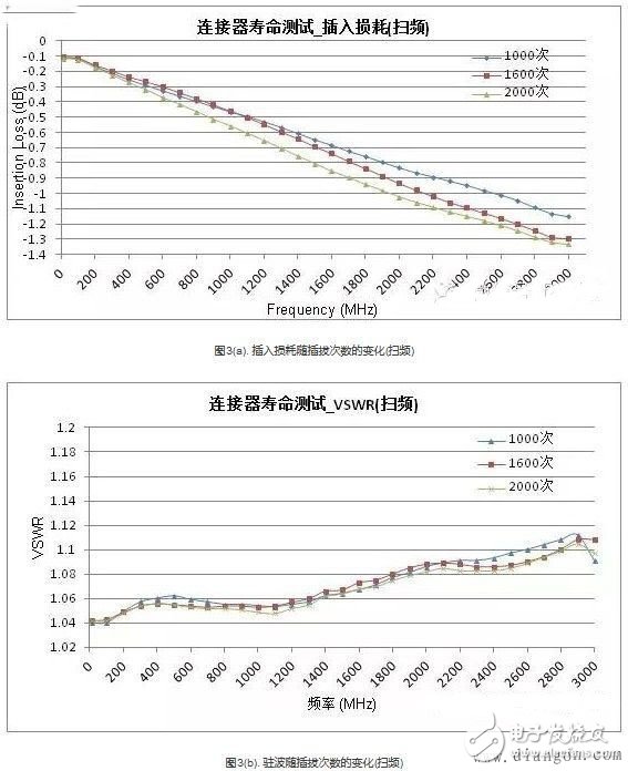
Life test resultThe final test results are shown in Fig. 2 and Fig. 3. Fig. 2(a) shows the insertion loss of the cable assembly at 2.2 GHz with the number of insertions and removals. Fig. 2(b) shows the number of standing waves with the number of insertions and removals at 2.2 GHz. Variety.

The red trend line in Figure 2 shows that although the measured values ​​fluctuate somewhat, the insertion loss of the cable assembly always increases with the wear of the joint; while the standing wave has no obvious deterioration, and its typical value is always maintained at 1.07~1.09. between.
Figure 3 shows the insertion loss and standing wave variation under sweep conditions, and records from 10 MHz to 3 GHz in the case of 1000 insertions, 1600 cycles and 2000 cycles, respectively. The sweep results show that the insertion loss and standing wave variation characteristics are consistent with the point frequency over the entire operating frequency band.
in conclusion1. Although the above test is only for one RF connector, some conclusions can still be drawn from the test results:
2. Under the premise of normal use, the life of the RF connector will greatly exceed the standard value of 500 times; in the entire frequency band, no insertion loss and standing wave jump phenomenon are found at a certain frequency point.
3. The insertion loss value of the RF connector gradually increases with mechanical wear; while the standing wave has almost no change; from the process, there seems to be no obvious failure point, so if there is no obvious fault of the cable on the production line, A mandatory retirement system should be established to ensure test indicators.
The Hydrogel Screen Protector is made of imported material with TPU as the base material and is combined with hydrogel. It has super ductility and retractability, and can perfectly adapt to curved screens and screens with excessively curved edges, so as to fit perfectly without leaving white edges, and basically does not affect the touch experience. It has a strong and effective self-healing function, is impact-resistant, durable, and has better toughness, and has a certain buffering effect on the collision of sharp objects.
The Hydrogel Screen Protector uses glue and hydrogel to activate the stickiness to ensure a perfect fit without warping and leaving blanks, which is more beautiful. The Hydrogel Film is very thin. The responsive, ultra-thin design gives you a bare-bones experience. It's not as thick as a Tempered Glass Screen Protector, so the hydrogel screen protector won't affect the weight and feel of the phone.
In terms of hand feel, the Hydrogel Screen Protective Film has a hydrophobic and oleophobic treatment, so it slides relatively smoothly, and there is no problem in using APP or playing games. In addition, the liquid spilled on it can be slipped off by just tilting it, which is very easy to clean and maintain.
Mobile Screen Protectors,Matte Hydrogel Protector,Anti Blue-Ray Hydrogel Film,Anti-Spy Hydrogel Film,Uv Curing Glass Film
Shenzhen TUOLI Electronic Technology Co., Ltd. , https://www.hydrogelprotector.com