Ripple is the core indicator of power, but how to accurately measure ripple is indeed a widely overlooked problem. Maybe you think that is not the oscilloscope AC coupling, and then point the probe on the power supply? This is far from the truth. This article presents you with the correct way to test the ripple.
First, the choice of probe
More than a decade ago, many companies had clear regulations on power test standards that required measurements using a 1:1 probe. Because this probe does not lose the measurement position of the oscilloscope, for example, the original minimum position of the oscilloscope is 2mv/div, and the ripple can still be measured through this gear with the 1:1 probe, that is, the ripple within 10mv can be accurately measured. . However, since the bandwidth of this type of probe can only be about 6MHz, this probe is no longer suitable for use as the frequency of the switching power supply increases.
The commonly used power measurement probes are 10:1 passive probes, 100:1 passive probes, and high voltage differential probes. The choice of probe must first consider the voltage range, and the measured voltage should not exceed the allowable range of the probe. For example, a typical 10:1 passive probe has a low-frequency withstand voltage of 300VRMS and decreases with increasing frequency, as shown in Figure 1. The voltage range to be measured before use is within this range, otherwise the correct measurement will not be possible.
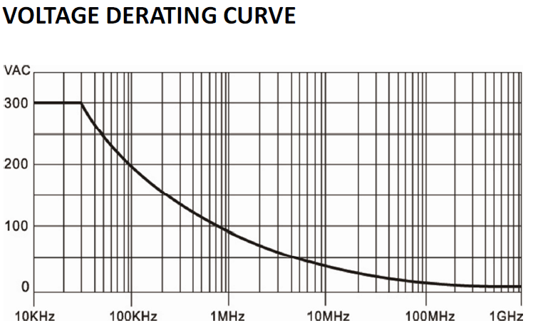
Figure 1 10:1 passive probe input rated voltage curve
In addition, it is necessary to consider the amplification of the probe attenuation ratio to the noise floor to determine the true and effective part of the signal. The schematic diagram when using the probe measurement is shown in Figure 2, where Gn1 is a virtual noise source, indicating the low noise of the oscilloscope, and Gn2 is the noise floor of the probe. Since the signal is attenuated by the probe, in order to restore the size of the real signal, the oscilloscope will further amplify the signal, and then Gn1 and Gn2 will be amplified, and the amplification factor is the reciprocal of the attenuation ratio. Therefore, the larger the attenuation factor, the more the noise floor of the measurement system is amplified.
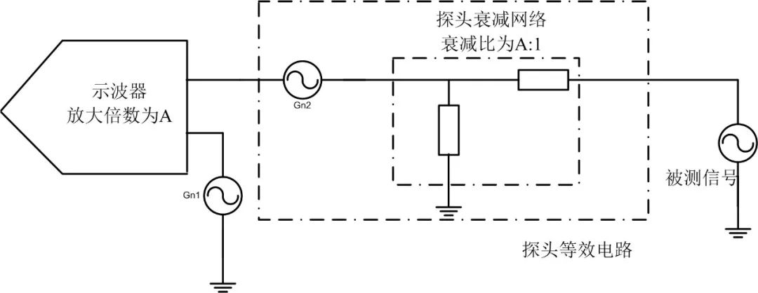
Figure 2 bottom noise amplification diagram
For example, using a 500:1 high-voltage differential probe for measurement, the oscilloscope noise floor is 1mv, the probe noise is 1mv, so the accumulated noise is 2mv, and after 500 times amplification, the noise floor reaches 1V. At this point, you need to consider whether the noise of 1V is within the allowable range. If the ripple of your system under test is only 1V or less, the noise of 1V is obviously not allowed.
Second, the choice of grounding method
Traditionally, the grounding method of the oscilloscope is the long grounding wire. As shown in Figure 3, this grounding method is indeed a simple and convenient grounding method, but it is not a rigorous and accurate grounding method.
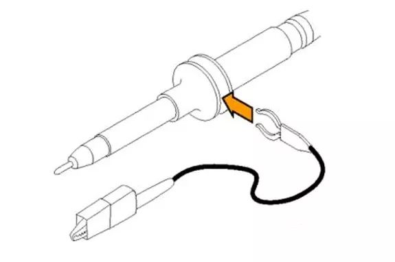
Figure 3 Grounding clamp diagram
Since the ground clamp wire is long, it will form a parasitic inductance Lgnd. As the clamp wire grows, this inductance will also increase, and this loop inductance will resonate with the input capacitance Cin of the oscilloscope probe. This causes the amplitude-frequency characteristics of the oscilloscope to become uneven, resulting in inaccurate measurements. Its equivalent circuit is shown in Figure 4:

Figure 4 Grounding clamp line equivalent circuit diagram
But this is not the most deadly grounding wire. Switching power supply, with the opening and closing of the switching tube, not only generates power supply ripple, but also generates a lot of electromagnetic interference, radiating through the space, and this part of the radiation will be received by the grounding clamping line and the coil formed by the probe. In addition, the oscilloscope is a high-impedance input, which causes the interference of this part of the signal to be very impressive. Although electromagnetic interference can also be said to be a parameter of the power supply, but this part of the signal can not be accurately measured by the oscilloscope probe, the measured value is meaningless.
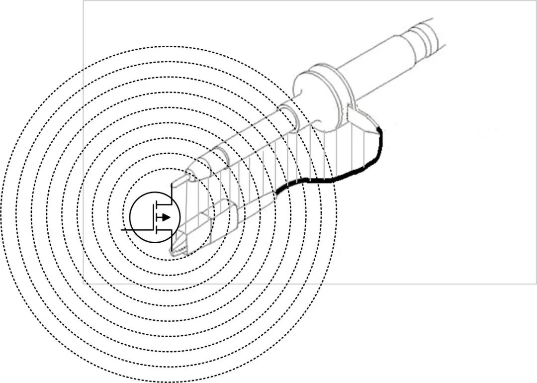
Figure 5 Schematic diagram of electromagnetic radiation
Because of the above two points, when testing the power supply ripple, the grounding wire should not be used, but the grounding spring should be used. As shown in FIG. 6, this reduces the loop inductance and ensures better amplitude-frequency characteristics, and reduces the introduction of electromagnetic radiation.
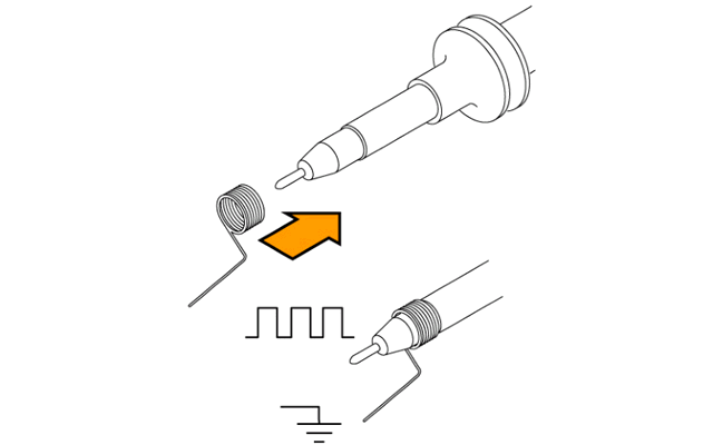
Figure 6 Schematic diagram of the grounding spring
If you are using a high-voltage differential probe, you should twist the two input wires together, as shown in Figure 7, to reduce the loop area.
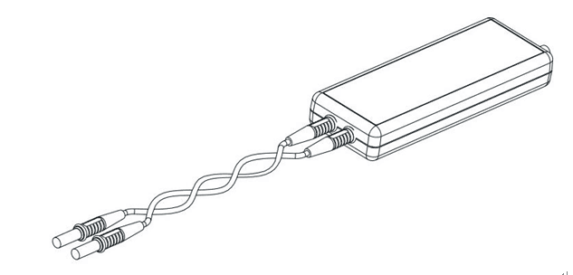
Figure 7: High-voltage differential probe input line twisted pair diagram
Third, the application of the filter
The above two cases are two ways to effectively enhance the authenticity of measurement results. However, in some cases, it is impossible to operate according to these two points. For example, using a high-voltage differential probe for measurement, there are generally two attenuation ratios to choose from: 50:1 (MAX 130V), 500:1 (MAX 1300V). If the measured voltage is 200V, then it is found that only 500:1 probe attenuation ratio can be selected. According to the calculation in the first part, the noise floor has about 1V, and the noise floor is somewhat too large, which will affect the final result. For example, in some measurement situations, it is inconvenient to fix the grounding spring, but it must be fixed by using the grounding clamp wire, but this will introduce a large amount of electromagnetic radiation interference.
This time you need to use a filter. The interference of noise and electromagnetic radiation is also the same as the normal signal, and it is also divided into frequency bands. If we filter out the noise of a part of the frequency band, we can greatly reduce the noise floor and radiation interference. But we don't want the signal of interest to be filtered out, which requires a low-pass filter.
The oscilloscope will have a 20M bandwidth limit function, in order to reduce the noise floor and radiation interference, the signal of interest is extracted from a bunch of chaotic signals. But as the frequency of the switching power supply increases and the frequency diversifies, a fixed 20M bandwidth limit is clearly no longer sufficient. To this end, the ZDS4000 Series oscilloscopes integrate a powerful digital filter function with a passband frequency that can be set arbitrarily up to 200MHz. Figures 8 and 9 show the effect of the filter on the noise floor and electromagnetic radiation interference.

Figure 8 Digital filter reduces the noise floor

Figure 9 Digital filter suppression of electromagnetic radiation interference
When you are measuring, you only need to estimate the frequency range you want to measure, and then set the digital filter to make your oscilloscope have a lower noise floor, making the measurement more accurate.
Fourth, the analysis of the results
After measuring the power supply ripple, the ZDS4000 oscilloscope also has many post-data analysis functions such as peak-to-peak statistics, maximum statistics, and minimum statistics. There is also a powerful FFT function. We can use the FFT function to perform frequency analysis on the obtained ripple waveform, so that the noise level at each frequency point can be accurately known. In this way, the ripple caused by the switch can be obtained more accurately, as shown in Figure 10:
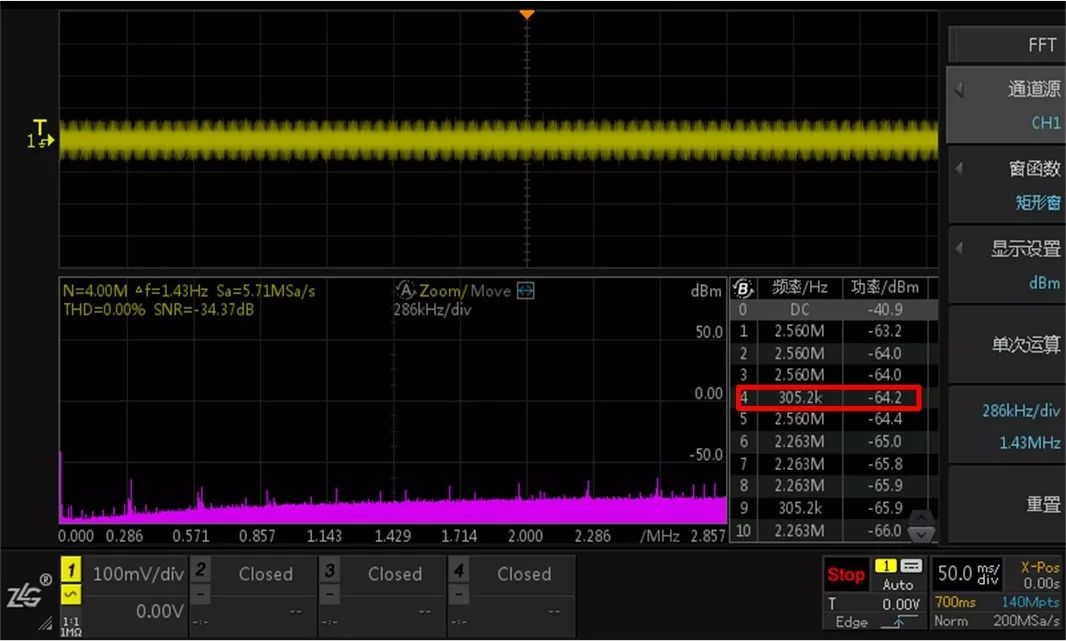
Figure 10 FFT analysis of ripple results
V. Summary
Some considerations for measuring power supply ripple are noted in this article and are summarized as follows:
1. The selection of the probe needs to be selected in combination with the withstand voltage range of the probe and the voltage range of the signal to be measured, and also consider the amplification effect of the probe attenuation ratio on the noise floor.
2, the choice of grounding method, should reduce the grounding loop as much as possible, such as the use of grounding springs. This can not only improve the amplitude-frequency curve, but also reduce the interference of electromagnetic radiation.
3. Flexible use of digital filters to extract the signals we need from the “noisy†noise, making the structure more accurate.
4. Through the post-analysis function of FFT, the noise level on the switching frequency can be measured more accurately.
The above is the main content of this article. With a flexible digital filter and powerful FFT capabilities, the ZDS4000 oscilloscope is perfect for most power measurement scenarios. At the same time, the ZDS4000 oscilloscope also has a powerful loop analysis function, which can perform further loop analysis on the power supply, so that the power supply can balance stability and fast response.
APM lab DC Power Supply is designed to provide continuously variable output voltage and current for a broad range of applications in a compact 1U and 2U high ,19" standard rack mounting. The front panel layout makes the laboratory dc power supply easy to use.
Some features of the high voltage dc power supply as below:
- Ultrafast respond time and high efficiency
- Accurate voltage and current measurement capability
- Constant Power and wide range of voltage and current output
- Equips with LIST waveform editing function
- Compliant with SCPI communication protocol
- Support RS232/RS485/LAN/USB (standard) ,GPIB (optional)
- Master/Slave parallel and series operation mode for up to 10 units
- Built-in standard automobile electrical testing curves
- Full protection: OVP/OCP/OPP/OTP/SCP
- Voltage drop compensation by remote sense line.
- Have obtained CE,UL,CSA,FCC.ROHS
200V DC Power Supply,DC Switching Power Supply,Adjustable Power Supply,Digital Control Dc Power Supply
APM Technologies Ltd , https://www.apmpowersupply.com