Resistor selection in almost all power supply designs has different feature priorities and performance requirements, including the need for resistors that can handle high voltages, high currents, and high power, as well as resistors that require low tolerances. This article will focus on using resistors to regulate power output and protect the power supply from failure.
There are a variety of power supplies on the market, and the variety of resistors used in these power designs has greatly expanded the range of choices. For the sake of clarity, the power supply referred to herein refers to a power supply device having a fixed DC output of up to several kilovolts.
Regardless of the application, the power supply designer must understand the specific safety or environmental regulations in the field in which it is applied, as well as the actual electrical performance. This article will focus on using resistors to regulate power output and protect the power supply from failure.
The classification of the power supply usually depends on whether the input is ac or dc, and what type of regulation is used to provide the correct dc output, usually a switch mode or a linear mode.
The line frequency voltage is usually supplied by the AC-DC power supply, while the battery or any other DC power supply provides DC-DC power supply. These DC-DC converters use switching mode technology to regulate the input voltage to a higher (boost) or lower (buck) output voltage.
Off-the-shelf power supplies are suitable for many markets and general uses, but in some cases require custom designs.
Linear Regulator
To understand the role of components in the power supply, it is necessary to understand the basic principles of power supply operation. Many engineers remember to design a circuit as shown in Figure 1. This circuit uses a Zener diode to provide a constant voltage to the load (R2). R1 is used to provide the minimum current to keep the Zener diode in a constant breakdown state and provide load current.

Figure 1: A simple Zener diode regulator circuit.
This type of system is suitable for circuits with low power and very stable supply voltages and loads. If the load current decreases or the supply voltage suddenly increases, the power consumption of the Zener diode may be exceeded. The resistance in this circuit is easily selected as long as its rated power meets the combined power requirements of the Zener diode and the load.
For power supplies with varying supply voltages or loads, the series design can use pass transistors, which will ensure that the load current is stable and the voltage output can be reduced to the desired range.
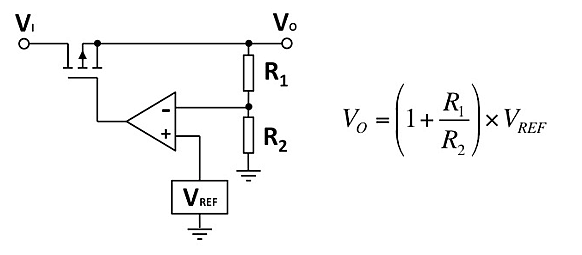
Figure 2 shows this circuit. These designs typically use ICs or low-dropout (LDO) regulators to regulate the load power. The voltage divider formed by R1 and R2 senses and sets the voltage output relative to the reference voltage. If the circuit has a fixed output, the voltage divider is internal; for other applications, one or two resistors can be placed externally.
The resistance value is chosen to provide the desired ratio. The most important consideration is accuracy. If the comparator circuit has high gain and high input impedance, you can use the formula in Figure 1 to easily calculate the worst-case value, first select the R1 maximum and R2 minimum, and then select the R2 maximum and R1 minimum. These calculations can show the maximum voltage deviation from the desired output.
Switching power supply
Since both the serial transmission device and the load consume energy, the linear power supply may be less efficient. As the pressure drop on the load increases, the efficiency will be lower.

Figure 2: Schematic diagram of a linear series regulator.
To improve efficiency, designers often use another power topology. The switching power supply (SMPS) uses an unregulated input DC voltage and switches at a high frequency (10kHz to 1MHz). The duty cycle determines the rectified and smoothed DC output voltage.
SMPS output adjustment also uses a voltage divider, but to adjust the switching frequency and duty cycle. By avoiding the loss of linear regulator voltage drop, SMPS can achieve up to 95% efficiency. Due to the much smaller size of high-frequency transformers and filter/storage capacitors, SMPS may also be more compact than similar power linear AC-DC power supply designs.
The main disadvantage of SMPS is that it requires a minimum load and that the no-load condition may damage the power supply. To avoid this situation, designers often use a power resistor as a dummy load. If the main load is disconnected, this resistor can be used to absorb the minimum specific load current. Of course, the dummy load resistor also has power consumption, which affects the overall power supply efficiency, so this factor needs to be taken into consideration when selecting the resistor. Another way to circumvent this problem is to use a shunt resistor at the output when the load is open. For safety purposes, other resistors are also used in the SMPS design. Low resistance, high power resistors usually prevent overvoltage conditions. The current limiting design prevents short circuits.
This type of switching technology can also be used in DC-DC converter designs to adjust one value of a DC voltage to another value. The buck converter works very similar to the aforementioned SMPS design. Boost converters use charge pump technology to output higher voltages than the input. Both technologies use similar methods to regulate the output voltage and provide circuit protection.
Other uses of resistors in power supply design
The discharge resistor is mainly used to discharge the capacitor in the circuit. They are in parallel with the load and are used in the AC-DC and DC-DC converters to discharge the smoothing capacitor and the storage capacitor, respectively. After the power is turned off, the capacitor is kept in a charged state, which may cause damage to the user and therefore require discharge. When selecting resistors for this task, there are two trade-offs: they should have a sufficiently high resistance so that they consume little power when the circuit is operating, and low enough to rapidly discharge the capacitor.
Surge limiting resistors limit the amount of inrush current AC-DC power supplies can cause when they are first turned on and the storage capacitor is charged. These resistors usually have low resistance and are in series with the AC power line. For higher power supplies, negative temperature coefficient (NTC) resistors are often used for this purpose. The resistance of these resistors decreases with self heating. One disadvantage of using such a resistor is that the temperature must be kept constant during operation to ensure that it is maintained at a low value. The third solution is to use pulse-resistant resistors, the power of these resistors is usually in joules. It can better describe its function than the normal continuous power scale in watts.
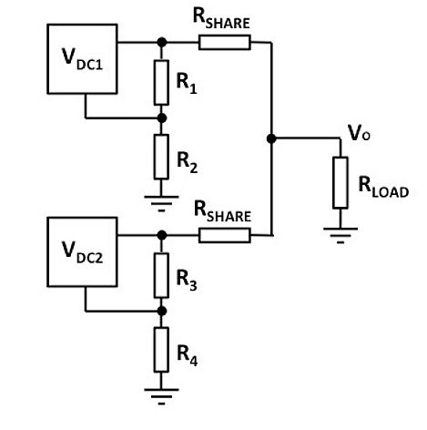
Balancing resistors are used to modulate the load current when using multiple power supplies. In general, using multiple DC-DC converters in parallel can be cheaper, more energy efficient, and more compact than using a single high power, large power supply. When designing such circuits, the outputs cannot simply be connected together, and a method must be used to ensure even load sharing. Figure 3 shows that the RSHARE resistor fills in the difference between the converter outputs.

Figure 3: Balancing resistors share the load between DC-DC converters.
This load sharing method is also used for other types of power supply designs, especially those using power transistors. Multiple transistors are connected in parallel to supply the load, and load distribution resistors are used in series.
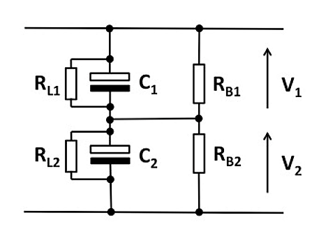
Another situation that needs balance is shown in Figure 4. In this case, the storage capacitor is in series with the DC power output. The leakage current of the electrolytic capacitor acts like a resistor in parallel with the capacitor, such as RL1 and RL2 in the figure. These resistances can vary considerably, and because they act as a voltage divider across the output, this can cause the voltage across the capacitor to exceed the capacitor rating. Matched resistors RB1 and RB2 cancel out this effect.

Figure 4: The balancing resistor ensures that the voltage across the output capacitor is equal.
The high voltage divider is used to provide feedback to the regulation circuit. These resistors usually have other secondary effects, such as monitoring the high voltage power supply in the defibrillator and charging the energy storage capacitor and turning off the power at the desired charge level.
High current detection is used to measure the supply current. This measurement method uses the principle of a shunt ammeter and requires a low value resistor in series with the voltage drop across it to calculate the current magnitude. This type of circuit design must consider the selection of resistors. On the one hand, low resistance is required to minimize heat generation and power dissipation. On the other hand, high impedance is required to facilitate measurement.
to sum up
Resistor selection in almost all power supply designs has different feature priorities and performance requirements, including the need for resistors that can handle high voltages, high currents, and high power, as well as resistors that require low tolerances. It is also usually required that the resistor have specific properties such as surge suppression capability or negative TCR.
Stainless Steel Mirror Strap,Stainless Steel Joining Strips,Stainless Steel Divider Strips,Stainless Steel Strip For Floor
ShenZhen Haofa Metal Precision Parts Technology Co., Ltd. , https://www.haofametals.com