Abstract: This system realizes the function of car black box based on Zigbee radio frequency technology with MG2455 microprocessor as the core. It can store operation and status information (such as time, temperature, tire pressure, etc.) at different times during the running of the vehicle, and if the indicator exceeds the normal range, it will alarm. When driving data is required, data can be directly read to the computer via the USB interface.
This article refers to the address: http://
0 Preface
The automobile black box is also called the vehicle driving state recording system, and is mainly composed of a vehicle driving state recorder, a handheld code reader and a management computer. The recorder is installed in the car to monitor and record the driving data of the vehicle in real time; the handheld reader consists of a handheld computer and application software for controlling and operating the recorder and reading data from the recorder through the RS232 serial port. The management computer is used to perform statistics, reports, storage, and queries on the original recorded data.
1 System principle and structure
1.1 System Introduction
The system uses the MG2455 microprocessor as the core, and designs a car wireless black box based on Zigbee wireless radio frequency technology. The tire pressure and tire temperature are detected by Zigbee technology and communicate with the host computer. The system includes a wireless monitoring transmission device mounted on the tire rim and a digital receiving and displaying device that can be installed in the vehicle body driver's seat. When the tire pressure and tire temperature exceed the standard, the system will give an alarm.
The system also has the function of prompting alarm and recording of fatigue driving, thereby effectively curbing the driver's fatigue driving and ensuring the safety of long-distance transportation.
1.2 Functions and indicators
(1) Store the operation and status information (such as temperature, tire pressure, etc.) at different times during the running of the vehicle and display it on the LCD screen. The stored frequency is 30 times/hour.
(2) The reference value can be set arbitrarily, and the indicator will alarm if it exceeds the normal range.
(3) When driving data is required, the data can be directly read to a personal terminal such as a PC or PDA through the USB interface. The USB interface is a universal USB 2.0 interface.
1.3 Principle of implementation
In the control system with the single chip as the core, all the processing of the car signal and the liquid crystal display are processed by the MG2455 single chip microcomputer. The sensor signals such as tire pressure and acceleration are transmitted to the single chip microcomputer through Zigbee wireless communication after A/D conversion. The wireless monitoring transmission device includes: a pressure sensor, a temperature sensor, a differential amplifier connected to the pressure device, an attenuator connected to the temperature sensor, a pressure signal received from the differential amplifier, and a temperature signal from the attenuator A microcontroller that performs arithmetic processing, and transmits the signal to the digital receiving display through a resonant antenna through a transmitter and a filter, so that the driver can grasp the tire pressure temperature condition at any time. The single-chip computer stores the clock signal and temperature signal received by the I/O port together with the wirelessly received tire pressure and acceleration signals in the flashROM and displays them on the LCD module LCD6029. When the signal exceeds the standard, the system can actively alarm. The USB interface is connected to the serial port of the MCU through the conversion chip, and the information stored in the system can be exported to a personal terminal such as a PC or a PDA.
1.4 hardware block diagram
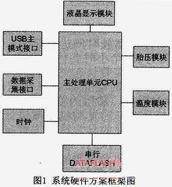
The system can be divided into data acquisition part, data processing part, data storage part, communication part (USB communication), display part, tire pressure module, temperature module and clock module. The hardware block diagram is shown in Figure 1.

1.5 Software Process
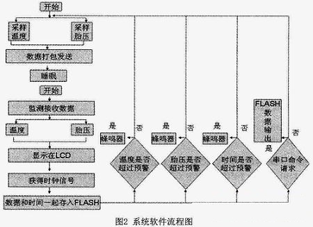
After receiving the data sent from the tire pressure monitoring module, the temperature module and the clock module, the main chip MG2455 is transmitted to the controller by the SPI port, and the controller also needs to check the data and complex algorithm while receiving the data. Process and judge the processed result. If the data exceeds the pre-determined range (such as overpressure, timeout, over temperature, etc.), the alarm will be activated immediately, and the buzzer will prompt the driver that there is an abnormality; otherwise, the car is running normally. In addition, the use of the serial port to achieve communication with the computer, easy to query and analyze the recorded data, to provide a basis for optimizing control algorithms and analyzing traffic accidents.
The system software mainly completes two functions: 1) Real-time detection and recording of the driving state of the vehicle, and alarm when a fault is detected. 2) Upload the recorded data to the host computer through the RS232 port for daily management and accident diagnosis.
The program mainly includes: main program, digital acquisition program, switch acquisition program, pulse quantity acquisition program, data storage program, clock processing program, fault processing program, fault alarm program and serial communication program.
The main program flow chart is shown in Figure 2.

2 system test
2.1 Test data
According to the data analysis, for every 1 °C increase in the tire, the tire wear increases by 2%, and the general temperature cannot exceed 80 °C. When the temperature reaches 95 °C, the tire condition is very dangerous. Moreover, the air pressure is too high, the tire cord is excessively stretched, the carcass elasticity is lowered, the rigidity is increased, the unit pressure is increased, the ground contact area of ​​the crown portion is reduced, and the wear is increased, the tread pattern is easy to crack, and the obstacle is impacted during driving. It will cause internal cracking or blasting. At the same time, the system is equipped with fatigue driving (time monitoring), so the system will give an alarm when the tire tire pressure temperature exceeds the preset value and the driving time exceeds 4 hours. In terms of errors during transmission, the tire pressure measurement accuracy is ±0.5 kPa and the tire temperature is ±1 °C.
2.2 Implementation functions
(1) It has the functions of collecting, recording and storing time, date and driving time. It can record the continuous driving time. Because the traffic safety law stipulates that the driver should rest for no less than 20 minutes every 4 hours, it can monitor the fatigue state of the driver. If the violation is found, an alarm will sound and the alarm will sound. This information will be transmitted to the monitoring center. (2) Temperature, tire pressure measurement, recording and storage functions: a. The temperature measurement system detects the engine temperature of the vehicle and displays it in real time, which can alarm the abnormal conditions of high temperature, thereby improving the driving. Safe line. b. The main function of the tire pressure and temperature detection system is to monitor the pressure and temperature data inside the tire and display it in real time, which can alarm the abnormal conditions of high pressure, high temperature and low pressure, thus improving the safety of driving. c. The running data is stored in the large-capacity serial flash memory, and the data is not lost even if the power is turned off. d. The USB interface is configured, and the data can be directly read by the U disk or connected to the computer.
3 Conclusion
The system has the functions of collecting, recording and storing time, date and driving time; car tire pressure and temperature.
The monitoring system communicates with the host through Zigbee radio frequency technology; the flash memory stores data, even if the power is lost, the data is not lost: the USB interface can be configured to read data directly from the U disk or can be connected to the computer for reading; Fatigue) alarm and recording function, which effectively curbs the driver's fatigue and ensures the safety of long-distance transportation.
The design passed the test and the system works well to meet the basic requirements of the car black box.
Steel Structures can be used in many industries such as foundation reinforce, electric power transmission structures and tubular scaffolding, etc.
A flange can also be a plate or ring to form a rim at the end of a pipe when fastened to the pipe. A blind flange is a plate for covering or closing the end of a pipe. A flange joint is a connection of pipes, where the connecting pieces have flanges by which the parts are bolted together.
Although the word flange generally refers to the actual raised rim or lip of a fitting, many flanged plumbing fittings are themselves known as 'flanges':
There are many different flange standards to be found worldwide. To allow easy functionality and interchangeability, these are designed to have standardised dimensions. Common world standards include ASA/ASME (USA), PN/DIN (European), BS10 (British/Australian), and JIS/KS (Japanese/Korean). In the USA, ANSI stopped publishing B16.5 in 1996, and the standard is ASME B16.5
Steel Structures Carport,Substation Steel Structure Fabrication,Peb Steel Structure,Light Steel Structure
Yixing Steel Pole International Trading Co., Ltd , https://www.yx-steelpole.com