Binary Phase Shift Keying (BPSK), also known as biphasic modulation, is a simple, popular digital modulation scheme. The symbol constellations are as far apart as possible, which is desirable for weak signal operation. BPSK is popular for its relatively simple spread spectrum capability. Therefore, BPSK can be applied to weak signal communication, spread spectrum, ranging and radar systems [1].
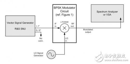
The LTC5548 is basically a passive double balanced mixer with a DC-coupled IF port. As a BPSK modulator (Figure 1), the mixer does not provide frequency conversion, so the modulator frequency range is limited to the range of frequencies that both the LO and RF ports can handle. Figure 2 shows the test setup for the BPSK modulator. A lab-level vector signal generator with a differential output will generate a baseband waveform.

Figure 1. RF mixer resistors R1 and R2 used as BPSK modulators each with an IF input of 50Ω, suitable for driving with modern laboratory test equipment.

Figure 2. Test setup for the BPSK modulator
Modulator IF input signal
The baseband drive level of the LTC5548 DC-coupled IF input should meet the following criteria:
The drive should always be differential (balanced) with a 0.0V common mode.
The typical drive level for each IF pin can be ±0.1V continuous (0.2V pp).
The drive level of each IF pin should not exceed ±0.2V at the peak signal (0.4V pp).
The drive level of each IF pin must not exceed ±0.3V absolute maximum rating. Moreover, such large input signals typically produce unacceptably high spectral reproduction at the RF output.
For most applications, low LO leakage is required, which means that the dc offset voltage on the IF input pin should be close to zero volts. Typically, the LO leakage is in a phase that cannot be completely eliminated with DC offset adjustment. Therefore, using DC offset adjustment can reduce LO leakage, but it does not eliminate LO leakage.
Figure 3 shows the IF+ and IF-pin voltages that make up the differential IF input signal. The test circuit is shown in Figure 1. Note that the signal is a differential signal centered around approximately zero volts and meets the drive level criteria listed above.

Figure 3. Typical modulator drive waveform measured at the IF + and IF- input pins. Symbol rate = data rate = 5 Mbps.
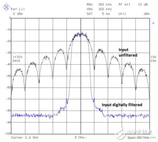
Applications that radiate BPSK signals over the air often benefit from digital filtering of baseband sources. In other applications, the modulated signal bandwidth may not be a problem and requires very little baseband filtering. Figure 4 illustrates the output spectrum of the modulator with and without baseband filtering.
Figure 4. Modulator output when driving with 5Mbps PN9 data. Pulse shaping provided by digital input filtering is very effective in reducing the output bandwidth. Here, the choice of the digital filter is the root raised cosine response, α = 0.35. The tracking average masks the 4.0dB peak-to-average ratio of the digitally filtered signal.
Example 1: 2.4GHz BPSK Modulator
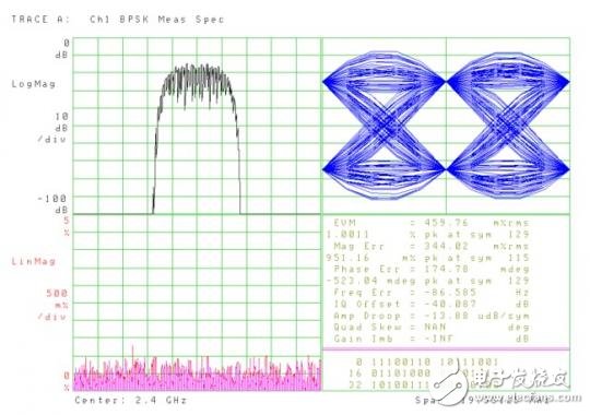
The Vector Signal Analyzer (VSA) measures the BPSK modulation accuracy of the LTC5548. The modulator schematic is shown in Figure 1. The drive for each differential input pin is shown in Figure 3. The test setup is shown in Figure 2. EVM measurements are better than 0.5% rms, which is satisfactory for BPSK communication systems.

Figure 5. BPSK modulation accuracy at 2.4 GHz The VSA measurement filter is the root raised cosine response, α = 0.35. Output power measurement - 2.6dBm.
Example 2: 8.6 GHz BPSK Modulator
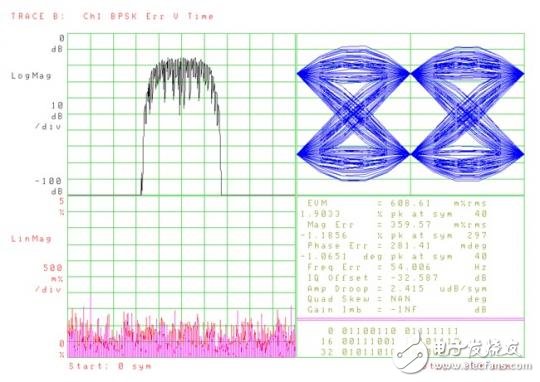
In the same circuit tested at 8.6 GHz, we saw a decrease in output power and an increase in LO leakage. The increased phase error can be attributed to an increase in phase noise of the LO at higher frequencies and a higher residual phase noise of the VSA at higher frequencies. For BPSK, the overall modulation accuracy of the EVM = 0.6% is still acceptable.

Figure 6. Modulation accuracy at 8.6 GHz The output power measurement is -5.8 dBm.
Example 3: 12 GHz BPSK Modulator Using Internal & TImes; 2 LO Multiplier
In this test, we increased the LO frequency to 12 GHz from the internal LTC5548 LO frequency multiplier. In this way, the test also includes any residual phase noise errors that the LO frequency multiplier may contribute. The external LO driver is 6GHz and X2 (pin 8) is tied high.
Compared to lower frequencies, the VSA only shows a slight, gradual degradation in performance. EVM is better than 0.8% and can be used in BPSK applications.

Figure 7. 12 GHz modulation accuracy using an internal LO&TImes; 2 multiplier. The output power is measured at -9 dBm at 12 GHz.
in conclusion
The EVM measurements show that as the LO frequency increases, the EVM and LO leakage (IQ offset) decreases slightly, but the performance of the BPSK application is still acceptable.
In the above three examples, the symbol rate = 5Msps. If operating at a higher LO frequency and a wider bandwidth (faster symbol rate), the EVM will increase due to the high frequency roll-off of the modulator RF port. For these high symbol rate (or high chip rate) applications, designers should make their own measurements to confirm that modulation accuracy is still acceptable.
[1] For example, CDMA, GPS, WiMAX, WLAN, ZigBee, and the like.
Aegis Series Vape is so convenient, portable, and small volume, you just need to take them out of your pocket and take a puff, feel the cloud
of smoke, and the fragrance of fruit surrounding you. It's so great.
We are the distributor of the GEEKVAPE brand, we sell GEEKVAPE Aegis Series Vape, GEEKVAPE Sonder U Vape, GEEKVAPE Z Series Vape, and so on.
We are also China's leading manufacturer and supplier of Disposable Vapes puff bars, disposable vape kit, e-cigarette, vape pens, and e-cigarette kit,
and we specialize in disposable vapes, e-cigarette vape pens, e-cigarette kits, etc.
geekvape aegis vape,geekvape aegis vape pod starter kit,geekvape aegis vape mod,geekvape aegis max vape kit,geekvape aegis vape device
Ningbo Autrends International Trade Co.,Ltd. , https://www.ecigarettevapepods.com
