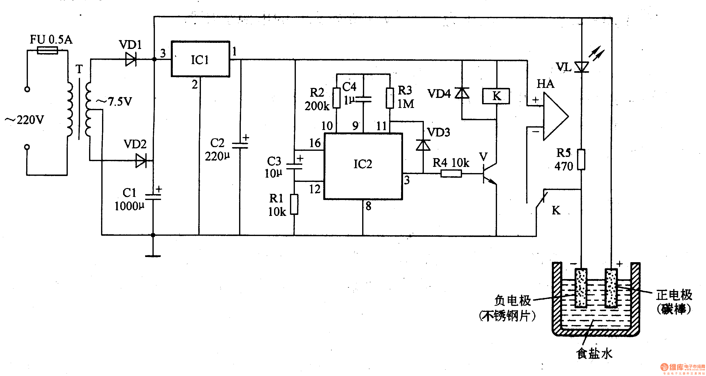
Circuit Operation Principle The disinfectant generator circuit consists of "power circuit, timer circuit, control circuit, sound and light circuit and electrode pads, as shown in Figure 9-92.

The power circuit is composed of a fuse FU, a power transformer T, a rectifier diode VD1, a VD2, a three-terminal integrated voltage regulator IC1, and filter capacitors Cl and C2.
The timer circuit is composed of a circuit in the counter/divider integrated circuit IC2 and its peripheral components.
The control circuit is composed of a transistor V, a relay K, a diode VD4, and the like.
The acoustic photoelectric routing alarm HA, the power indicating LED VL and the current limiting resistor R5 are composed.
Turn on the power, AC 220V voltage through T step-down, VDl and VD2 full-wave rectification, Cl filter, generate +7.5V voltage. The voltage is directly applied to the positive electrode sheet; one way is regulated by IC1 to +5V, and is supplied to IC2, relay K and alarm HA; the other is applied to the working pole of the light-emitting diode VL.
At the moment when the power is turned on, the 12-pin of IC2 generates a reset pulse, so that the internal circuit of IC2 is automatically cleared and reset, the oscillator and the divider work, the counter starts counting, the 3 pin of IC2 outputs low level, the transistor V is cut off, and the relay K If it does not work, its normally closed contact is turned on, the normally open contact is disconnected, and the light emitting diode VL is energized to indicate that the disinfectant generator is working.
When the timing time (about lh) is over, IC3's 3 pin goes high, so that the internal oscillator of IC2 stops, the transistor V saturates and turns on, the relay K acts, its normally open contact opens, and the electrode is cut off. The power supply circuit causes the VL to be extinguished and the disinfectant generator to stop working; at the same time, the normally open contact of the relay K is turned on, and the alarm HA is energized to remind the user that the disinfectant has been prepared.
The timing can be changed by changing the resistance of the resistor or changing the capacity of the capacitor C4.
Component selection
Rl-R5 selects 1/4W film resistor for use.
Cl-C3 selects aluminum electrolytic capacitors with a withstand voltage of l6V; C4 uses polyester capacitors or monolithic capacitors.
Both VDl and VD2 use lN5401 silicon rectifier diodes; VD3 and VD4 select 1N4148 silicon switching diodes.
VL uses φ5mm red or green LEDs.
V selects S9013 or 3DGl2 silicon NPN transistor.
ICl uses the LM7805 three-terminal integrated voltage regulator; IC2 uses a 14-bit binary serial counter/divider IC integrated with the CD4060 or MCl4060 built-in oscillator.
T selects 20-25W, the secondary voltage is double 7.5V (with plug) power transformer.
HA uses an electromagnetic sounder with its own sound source.
K selects JZC-22FA (5V) ultra-small medium power relay.
The electrode can be made by itself: the positive electrode uses the carbon rod inside the dry battery of the No. 1 and the negative electrode is made into a "U" shape by using a stainless steel piece; the positive and negative electrodes are fixed on the plexiglass plate and then placed in the plastic measuring cup; the electrode and the lead wire are The joint is sealed with hot melt or epoxy glue.
4000 Puffs Vape,Colored E-Cigarette,Electronic Cigarettes Vape,Vape Pen Vaporizer
Guangzhou Yunge Tianhong Electronic Technology Co., Ltd , https://www.e-cigarettesfactory.com