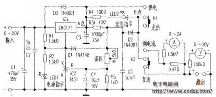
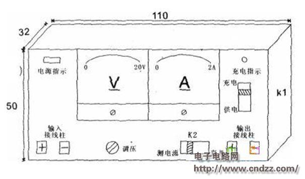
The composition and component selection of the silicon photovoltaic panel voltage regulator charger: The above figure is the electrical schematic diagram of the self-made silicon photovoltaic voltage regulator charger. The following figure is a schematic diagram of its panel layout.
1. Ammeter and voltmeter: Disassembled from the left and right channel level indicator in the old stereo (the measured DC parameter is 230μA: 560Ω: the external dimensions are 35x33x10mm3).
2. The chassis uses a used switch power box that measures 110x50x32mm3.
3. The main components: three-terminal positive adjustable voltage regulator block LM317T: input 1.25V ~ 37V, output current: 1.5A. The precision regulated source TL431 is used as a voltage comparator sampling: input voltage 2, 5V, 36V, maximum current 100mA. K1 is the power supply charging switch.
Production:
1. The audio dB table is modified (the resistance to be connected in series and parallel is shown in the figure above): The relaxation of the headspring is set exponentially. When the voltmeter is reformed, the scale on the table can take 2/3 arc length from 0V to 10V, and take "the arc length is 10V ~ 20V, which corresponds to the deflection value of the pointer. Similarly, the current meter is modified. The dial scale can be drawn. A smooth piece of paper is attached to the original dial, and then connected with an adjustable power supply. The digital scale is used to actually detect and determine the scale value: first determine the 10V and 20V calibration lines, and then draw each segment according to the exponential law. Scale (for precision).
2. Circuit board production: Because there are not too many components, use a common insulating board to drill and weld (the board size is 40x30mm2, installed upright in the box, and the upper and lower covers are just closed). Apply a sealant or other glue to the soldering surface on the board for added strength. Some components can be supported by terminals, switches, and soldering pads. The LM317T should try to increase the aluminum heat sink, and all the connecting wires should be welded with a single strand thick wire of 0.5mm or more.
3. Charging calculation debugging: R3 is a current limiting resistor, and the formula R3=1.95V/charging current is calculated. In the formula, 1.95V is the sum of the starting voltage of 1.75V of LM317T and 0.7V of D2 junction voltage. When R3 is 10Ω, the charging current is about 200mA; when it is 7.5Ω, it is about 300mA. A 100Ω resistor can be connected to the dummy load during commissioning. Adjust W, determine the upper limit voltage (charge 3,6V lithium battery to 4, 2V; charge 7.2V lithium battery to 8.4V), remove 100Ω resistor after debugging. After the lithium battery is connected, the constant current and constant voltage charging state is entered, and the LED 2 is a charging indicator lamp (about 2V voltage formed between two points of the AB causes the LED 2 to emit light), and the charging current gradually decreases. The voltage between the two points is gradually reduced. After the battery is fully charged, the LED2 is extinguished. At this time, the trickle charge state is entered (the current meter can still see the small current indication), and after about 20 minutes, the battery is removed, and the effect is better.
This regulator can be made with other DC power supplies in addition to solar panels. For example, transformer mains rectification, switching power supply, acid lead storage battery, and the like.
The role of K2 in the regulator is to prevent the current meter from being burned out. For example, if a battery is not activated for a long time, the memory effect caused by the memory can not be charged. It needs to be activated repeatedly with a large current meter. If K2 stays in the “measuring current†position, the head coil will be burned... However, the LM317T does not burn out due to overcurrent protection inside. In short, this kind of clean energy for mobile phones, players, tablets, batteries, is also a good measure of energy conservation advocated by the country.


Aquarium Filters,Aquarium Filter,Filter For Aquarium,Aquarium External Filter
Sensen Group Co., Ltd.  , https://www.sunsunglobal.com