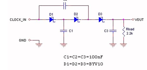
The voltage multiplier described in this design example is a modified version of the Dickson charge pump (Figure 1). Unlike that circuit, it does not require a DC input voltage, only a digital clock signal, and the DC voltage at the output can ideally reach twice the peak value of this clock signal.

Figure 1: The voltage multiplier can generate its own local positive voltage.
This circuit is actually a charge pump, in which C1 is first charged to the high level of the input clock, then discharged to C2 through D2 when the input clock is low, and C2 is discharged to C3 through diode D3 when the clock returns to high level. .
In the absence of a load, the output voltage is twice the peak input voltage minus the forward voltage of the three diodes - a total of about 0.75V. The output voltage settles in ten clock cycles; after two clock cycles, the output voltage reaches approximately 60% of the final value. The value depends on the load current and the peak value of the input clock, so if you want a precise output voltage, you can adjust it later.
To choose a capacitor value for a specific application, you can follow this formula:

Where Iload is the load current, Tlow is the duration of the clock low, and VR (PP) is the acceptable peak-to-peak ripple voltage at the output.
The above circuit was tested with a 200 kHz RC Schmitt non-stable multivibrator. The oscillator is built with a 74HC14 inverter operating at VDD = 5V (Figure 2). The oscillator output is connected to the input of the voltage multiplier via a 10m long twisted pair. The following is the result of the measurement:

D4 is used to minimize ringing on the falling edge of the input clock.

Figure 2: Clamping diode D4 with anti-ringing added.
This circuit draws energy from any digitized data line, so it can provide higher supply voltages in remote micropower applications that do not use local batteries, such as in single-wire serial interface networks.
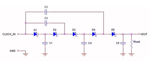
If a higher supply voltage is required, this circuit can also be extended to obtain an N-fold multiplier. Figure 3 is a three-fold multiplier.

Figure 3: Triple voltage multiplier.
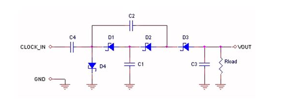
We can also generate a negative voltage by inverting all the diodes and coupling and clamping the input peaks to 0V through the capacitors. Figure 4 shows a negative voltage multiplier in which the clamping circuit consists of C4 and D4. It is also possible to obtain a higher negative voltage by modifying the circuit shown in FIG.

Figure 4: Negative voltage multiplier.
OEM Laptop Ram manufacturer Memoria Ram ddr 4 4g 2666 memory sodimm 4gb ddr4 2666mhz dual channel RAM for laptop 16c PC4 21300 1Rx8
• 240-pin, unbuffered dual in-line memory module (UDIMM)
Ddr4 Desktop Memory,Ddr3 4Gb 1600Mhz,Ddr3 4Gb Ram Game Memory,Ddr3 8Gb Desktop Memory
MICROBITS TECHNOLOGY LIMITED , https://www.hkmicrobits.com