Since the birth of the first radio transmitter, engineers have been concerned about RF power measurement, knowing that this is still a hot topic today. Power measurement is essential whether in the laboratory, on the production line or in teaching.
In the early days of radio development, most of the test engineers faced continuous wave, amplitude modulation, frequency modulation, phase modulation or pulse signals, which are regularly followed. For example, continuous wave (Fig. 1) power measurement of frequency modulation or phase modulation signal is very simple, only need to measure its average power; the power of the amplitude modulation signal (Fig. 2) is related to its modulation depth, and the characteristics of the pulse signal are Pulse width and duty cycle are expressed. For these analog or analog modulated signals, the RF power measurement is basically concerned with average power and peak power.
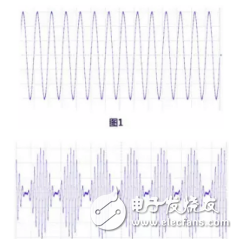
Now, especially after the 1990s, digital communication began to develop rapidly, and the focus of RF power measurement began to change. Because the envelope of the digitally modulated signal (Figure 3) is irregular, its maximum and minimum levels vary randomly and vary greatly. In order to describe the characteristics of such signals, new description methods such as pilot power, burst power, channel power, etc. are introduced. Many traditional power meters have been unable to meet the measurement requirements of digital signal power, and some of the power measurement tasks have begun to be completed by spectrum analyzers.

Below we introduce some common RF power measurement methods. Before we need to clarify one thing - why is it customary to use power to describe signal strength in frequency domain test measurements, rather than commonly used in time domain test measurements? Voltage and current? That is because in the RF circuit, since there are standing waves on the transmission line, the voltage and current lose uniqueness, so the size of the RF signal is generally expressed by power. The internationally-used power unit is W, mW, dBm.
Both the spectrum analyzer and the power meter can measure the RF power, and the power meter is divided into an absorption power meter and a pass power meter.
The same is the power measurement, the different focus of different test instruments and test methods are different.
RF power measurement method:
· Spectrum Analyzer Measurement · Absorption Power Measurement · Passive Power Measurement
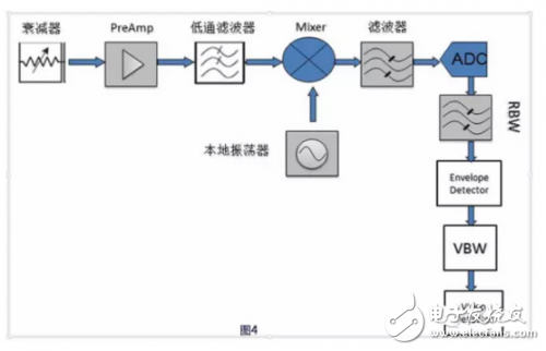
1, spectrum analyzer measurementThe spectrum analyzer (hereinafter referred to as the spectrum analyzer) is a basic frequency domain test and measurement instrument. Figure 4 shows the basic working principle of the digital intermediate frequency technology spectrum analyzer. The signal under test passes through the low-pass filter and enters the mixer, mixing with the local oscillator signal that simultaneously enters the mixer. Since the mixer is a nonlinear device, an intermodulation signal is generated, and the signal falling into the filter passes through the ADC, and then enters the intermediate frequency filter, the envelope detector, the video filter, the video detector, and finally displays the trace on the screen. on.
When performing RF power parameter measurement, the spectrum analyzer has the following characteristics:
1) The spectrum analyzer can measure the RF signal of a very small amplitude, depending on a key indicator of the spectrum analyzer - DADL (Displayed Average Noise Level), Chinese "display average noise level", such as RIGOL DSA875, the indicator is reachable - 161dBm/Hz, Figure 5 shows the DSA875 measuring a frequency of 999MHz, the power -130dBm signal results, the signal is clearly visible, which is beyond the reach of any power meter.
2) The spectrum analyzer has a large amplitude measurement range from DANL to safe input level +20 dBm or even +30dBm, and the dynamic range is up to 190 dB! At present, the maximum dynamic range of the power meter on the market is basically within 100 dB, such as:
A German company NRP8S: –70 dBm to +23 dBm
US company U2041XA: –70 dBm to +26 dBm
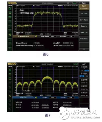
3) The spectrum analyzer can measure the frequency component of the signal and can perform narrowband measurements. For example, RIGOL's DSA875 has advanced measurement functions such as channel power and pilot power, as shown in Figure 6, Figure 7.
4) The spectrum analyzer can simultaneously measure multiple carrier frequency signals and observe the distribution of the signal spectrum analyzer.
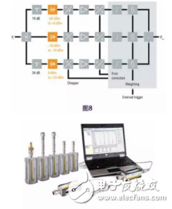
2. Absorption power measurementAbsorption power meters are commonly used microwave and RF power measurement devices. The working principle is shown in Figure 8 (Diode Detector Power Meter). The signal to be measured first enters the power meter. The power meter circuit can be constructed by different methods such as thermistor, thermocouple or diode detector. The power meter is composed of three measuring channels, which respectively measure signals of different power levels. After digital processing The power value is displayed to the power meter host or computer software, and now more and more display parts are implemented by software (Figure 9).
The absorption power meter has the following features:
1) In common microwave and RF power measuring instruments, the amplitude measurement accuracy of the absorption power meter is the highest;
2) The dynamic range generally does not exceed 100 dB;
3) It is not possible to measure high power. Usually, the upper limit of measurement is about +30 dBm (1 W). If it is necessary to extend the measurement range, an external attenuator is required.
4) It is possible to measure the average power, peak power, burst power, pulse width, rise/fall time of various modulated signals;
5) The frequency component of the signal cannot be measured like a spectrum analyzer;
6) VSWR cannot be measured.
In view of these characteristics of the absorption power meter, it is used as a laboratory calibration device for calibrating signal sources and spectrum analyzers.
3, pass measurementPass-through power measurement is an extended application of the absorption power measurement method, which solves the limitation of the absorption power meter measurement high power and VSWR. The biggest significance of the pass-through power measurement is that it can measure the matching of the amplifier or transmitter with the load under high power conditions. When it comes to pass-through power meters, many people think of a product, Bird 43 (Fig. 10), which was invented by Bird in 1952 and is still being used and applied.
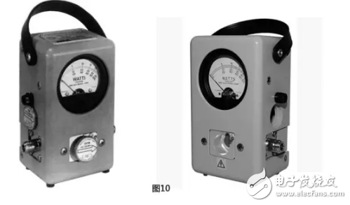
The core device of the pass-through power meter is a directional coupler. By measuring the forward power and reflected power of the power meter, the VSWR is calculated. This measurement method has the following characteristics:
1) Pass-through power meter has high power measurement capability;
2) It is not possible to measure the power with a small amplitude;
3) The pass-through power meter is limited by the bandwidth of the directional coupler, and the measurement bandwidth is much smaller than that of the spectrum analyzer and the absorption power meter;
4) The pass power meter can measure the high power matching between the transmitter and the load (antenna).
to sum up:It can be seen from the introduction of this paper that in the measurement of RF power, the spectrum analyzer has flexibility in its application range, and the absorption power meter has the highest accuracy. The pass-through power meter is more biased towards high-power signal measurement.
Closed Pod Electric Vape 3.5ml Pod
Closed Pod Electric Vape 3.5Ml Pod,2 In 1 Vape,Smoking Succedaneum E-Cigarette,Vaporizer E-Cigarette
KENNEDE ELECTRONICS MFG CO.,LTD. , https://www.axavape.com