Related topics:
(1) Measuring the pulse signal frequency f_O, the frequency range is 10Hz ~ 2MHz, the absolute value of the measurement error is not more than 0.1%. (15 marks)
(2) The duty cycle D of the pulse signal is measured, the measurement range is 10% to 90%, and the absolute value of the measurement error is not more than 2%. (15 marks)
Idea one: external interrupt
Idea: This method is easy to think of, and it is applicable to almost all MCUs (even 51). The method is also very simple, declare a count variable TIM_cnt, every time a rising edge/falling edge enters an interrupt, for TIM_cnt++, and then statistics can be. If the duty cycle is required, then a timer is used to count the time between the rising and falling edges.
Disadvantages: The defects are obvious. When the frequency increases, it will break into frequent and take a lot of time. And when the frequency exceeds 100kHz, the interrupt program time will even exceed the pulse period, resulting in a huge error. At the same time, what is more important is that the duty cycle that you want to measure is affected by the interrupt program and the error will increase.
Summary: We passed the plan to PASS for the first time. There is no relevant code (this code is also very simple). However, this method can be used to measure the frequency when the frequency is low (below 10K). At lower frequencies, the duty cycle can be measured.
Second idea: PWM input mode
Ideas: Check the ST reference manual, there is such a mode in the timer:
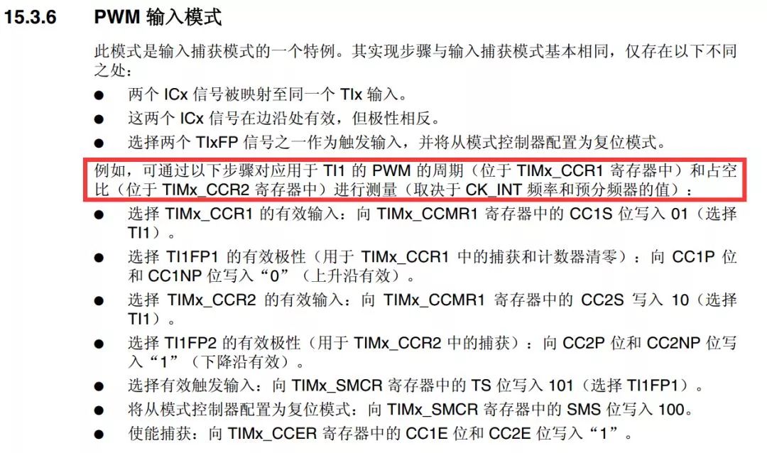
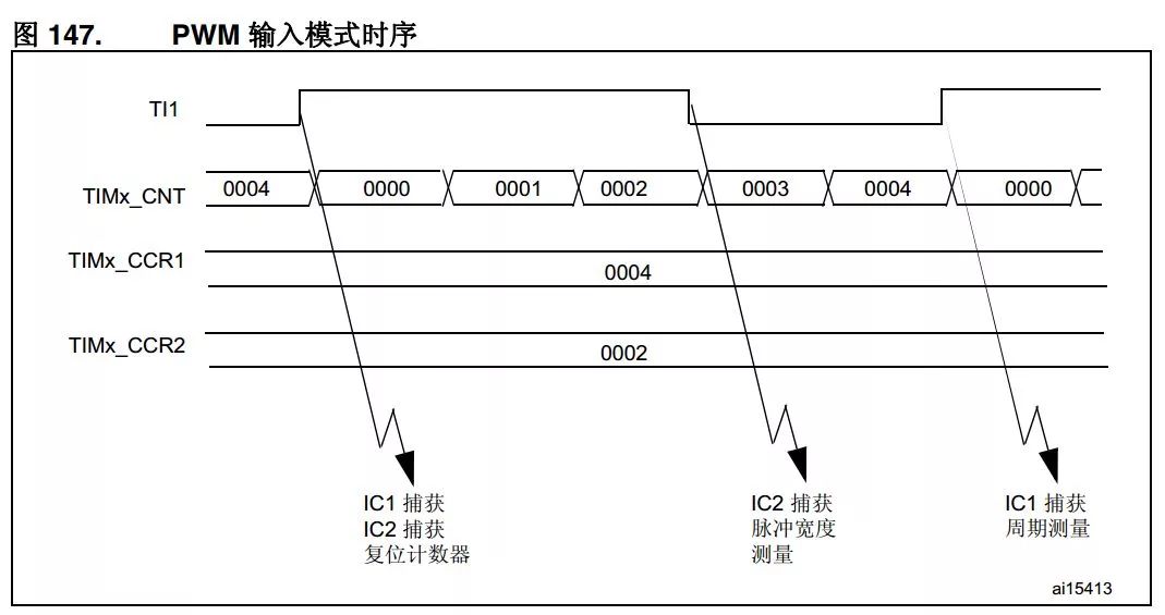
In short, theoretically, with this model, the frequency and duty cycle can be directly measured in hardware. At that time, we found this mode of rejoicing and thought that we could solve this problem in one step.
However, after the measurement, it was discovered that the test data of this method was unstable and inaccurate, and the data kept beating, and there was a large difference from the actual value. These functions of the ST often have such problems, such as the encoder mode of the timer, which may get stuck when there are frequent positive and negative transitions at 0 o'clock. Although these methods save time, the stability is not very good.
After linear compensation can reduce the error to a certain extent (the parameters are different under different conditions):
Freq=Frequency*2.2118-47.05;
This method cannot meet the requirements. So I do not recommend this method here. If anyone can have a better program, they are welcome to send it out.
(User Comments:
1. You have problems in the early stage, which may be related to the input filter. If you do not exceed 2 MHz in the measured signal, you may use the filter [0011: fSAMPLING=fCK_INT, N=8] as a good choice.
"These ST features often have this kind of problem" I have not encountered before, STM32 timer various modes I have used basically. 2, your input capture efficiency is too low, in addition, if it is really high frequency, the program should be dynamically based on the measured frequency value to modify the PSC, in order to achieve dynamic precision adaptation, input capture does not need every time Into the interrupt, 1MHz signal, you capture 1 million times per second, the value is equally meaningful? Can I capture 10 times per second to average? Just handle the details.
)
Three ideas: input capture
Ideas: In general, altarmates who have a certain understanding of STM32 often think of using input capture to measure frequency. First, it is set as a rising edge trigger, and the interval between the rising (rising) and the last interrupting (lasting_last) is recorded (period, and its reciprocal is the frequency). It is set as the falling edge. The difference between the time after entering the interrupt and the rising edge is the falling-rising_last. The high-level time divided by the duty cycle is the duty cycle.
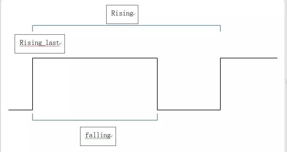
This method is especially good at low frequencies (<100 kHz).
Disadvantages: Slightly experienced friends should be able to see that this method still has a very high frequency of interruptions. At high frequencies, the first is that the CPU time is completely occupied, and, more importantly, too long interrupt program time often results in missing one or more interrupt signals. The performance is measured in the actual value, actual value × 2, Actual value x 3 beats. In actual measurement, the highest frequency can measure about 400 kHz.
Summary: This method has good accuracy at low frequencies (<100 kHz) and it is recommended to use this method below 10 kHz, taking into account other procedures. At the same time, you can refer to the following improvement procedures to reduce the CPU load.
Improve:
The aforementioned problem, the main factor limiting the increase in frequency is the long interruption time (under the general application scenario, there are other program restrictions). So make the following improvements:
1. Use two channels, one measuring only the rising edge and the other only measuring the falling edge. This can reduce the delay of the switching trigger edge. The disadvantage is that more than one IO port is used.
2. Use registers to simplify the program
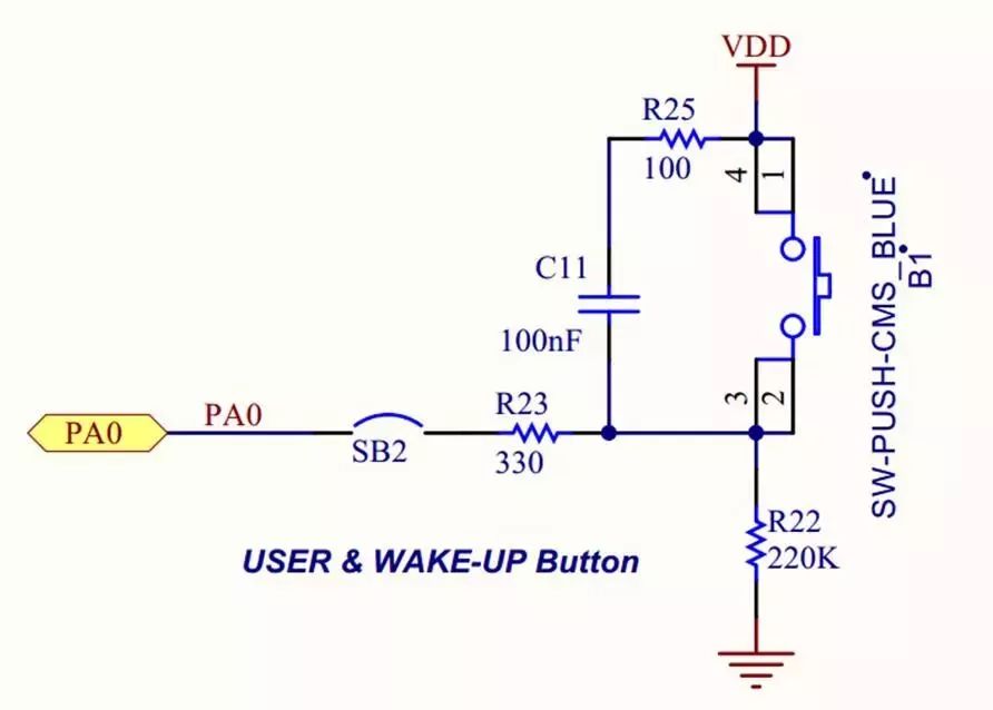
The reason for using TIM2 instead is because the TIM5's CH1 (PA0) is also a key input pin. Originally wanted to come here should be nothing, not press the button is not open. But later it was found that there was an RC filter on the official development board...
So, before using someone else's program, be sure to check the circuit diagram carefully.
In this way, the maximum frequency can reach about 1.1MHz, which is not a small improvement. However, its fundamental problem - too frequent interruption - still exists.
There is also a solution. Essentially, we actually only need to read the CCR1 and CCR2 registers. In the process of memory copying, what do we think of when we face the transfer of large amounts of data? Obviously, we can easily think of - using DMA. Therefore, we use the input capture event to trigger the DMA to move the register instead of triggering the interrupt, and then store the data in an array and cycle refresh. In this way, we can view the data and calculate the frequency at any time.
@xkwy Great God put forward several improvements in the reply, listed as follows:
1. It can be set that only the falling edge of channel 2 captures and triggers the interrupt, while the capture of rising edge of channel 1 does not trigger the interrupt. In the interrupt function, CCR1 and CCR2 are read at one time. This saves a lot of time.
2. A measurement can be performed first, and the prescaler value PSC can be changed according to the measured value to improve accuracy
3. Interval sampling. For example sampling 10ms every 100ms.
Such improvement should be able to increase the maximum sampling frequency to 2M. However, further improvement of the frequency is still not possible. Because the main contradiction at this moment is that the interrupt function takes too long, and the CPU is still processing the interrupt when this cycle ends, so that the final measured frequency is about an integer multiple of the true frequency. The schematic diagram is as follows:
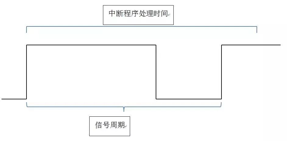
Therefore, the following method is still recommended at high frequencies.
The fourth idea: use an external clock counter
This method is the method I recommend when answering questions in the past few days. The idea is to configure two timers. Timer a is set to the external clock counter mode. Timer b is set to timer (for example, 50ms overflows once, and software timer can also be used). Then the timer b interrupt function count timer a. During this period of time, simply calculate it.
Disadvantages:
1. The duty cycle cannot be measured, and the high-frequency duty cycle measurement method is shown below.
2. In the case of low frequency, the measurement accuracy is inferior to the idea 3 (because the measurement period is 100ms, if the pulse period is 200ms...).
3. The input amplitude must exceed 3V. If it is not enough or exceeds, you need to join a preamplifier.
Summary: This method is very accurate, the measured error is 30Hz at 2MHz, which is 0.0015% (caused by the interrupt service program, you can use linear compensation correction), under the 25MHz error is about 30Hz (can not achieve a higher The reason is that the maximum output frequency of the waveform generator is 25MHz^_^). At the same time, the problem of excessively high interruption frequency was fundamentally solved. Due to the low-frequency problem, it is recommended that at low frequencies, either increase the sampling interval (changing the TIM7 cycle), or use the idea 3 input capture.
In addition, there is an inexplicable problem is that, if you do not join the sprintf (str, "% 3.3f", TIM_ExtCntFreq/1000.0) sentence, TIM_ExtCntFreq is always 0. I guess it's an optimization problem, but adding volatile is useless. If you don't have enough time, you won't ignore it.
Five ideas: ADC sampling measurement (probability measurement method)
In general high-end oscilloscopes, this is the method of measuring the frequency. In short, a series of data is sampled at high speed and then frequency is obtained by spectral analysis (eg fast Fourier transform FFT). The F4 has FPU and DSP instructions and is computationally fast. However, the ADC sampling frequency is far from reaching. The official manual states that up to 8.4M sampling rate can be achieved with three-channel alternating sampling + DMA. However, according to the Shannon Sampling Theorem, the sampling frequency must be at least 2 times the signal. The 2M signal and the sampling rate of 8.4M, even if calculated, are unacceptable. Therefore, ADC sampling cannot measure frequencies, especially high frequency frequencies.
However, the frequency cannot be measured, but the duty cycle can be measured, as well as the overshoot and rise time (the time the signal rises from 10% amplitude to 90%)! The principle is also very simple. The probability theory class has said this basic principle of probability:

When the number of samples n tends to infinity, the probability of event A is close to the frequency of statistics. Therefore, when the number of samples is larger, the frequency of the sampled high-level total number of samples approaches the probability-duty cycle!
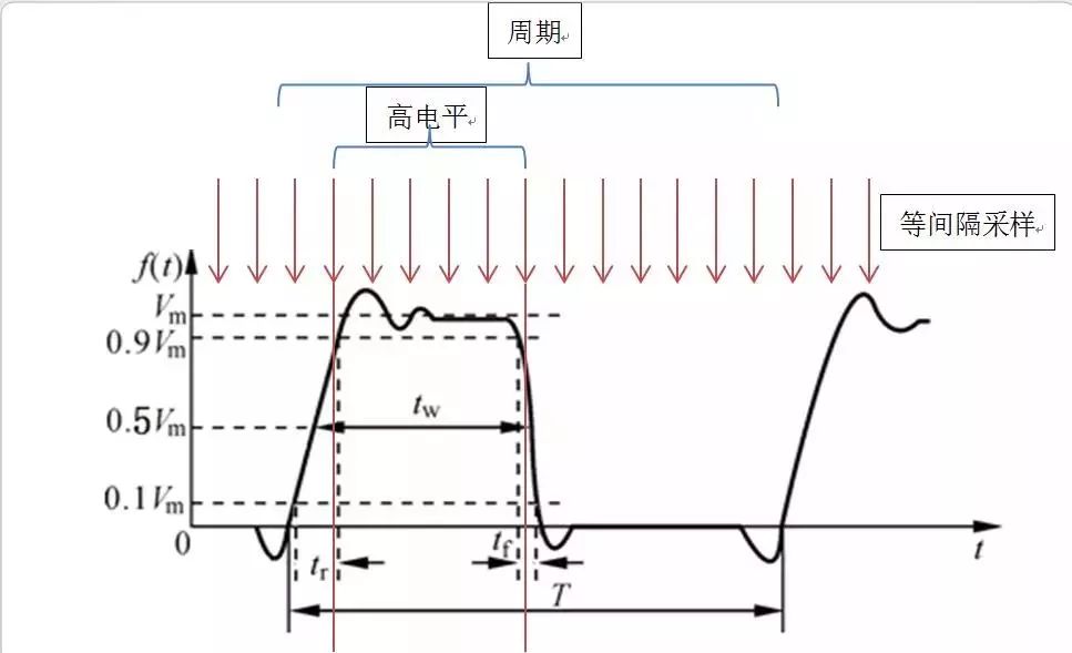
Therefore, the basic idea is to sample at equal intervals (the speed does not matter, but must be guaranteed to have equal probability sampling), and store these data in an array and repeatedly refresh. In this way, the data in the array can be counted at any time to obtain the duty cycle data.
Disadvantages:
1. Low Accuracy: The measured error is about 1.3% at 2MHz, and it cannot be counted at low frequencies (eg, frequency is 10Hz, and ADC sampling time is 50ms. At this time, if the sampling time is exactly high, the duty cycle is 1...) .
2. Large memory footprint: The data pool size is 65536, which occupies 64 KB of memory.
3. There is a response delay: Measured is the "average duty cycle" instead of "instantaneous duty cycle." Since I was using a waveform generator, the output waveform was quite stable (after all, the price of 1W+ was justified...). In practical applications, it is generally impossible to achieve such a level, and it is bound to bring about a delay in response. The greater the integral inertia of the sampling system is).
4. Amplitude too low (0.3V) cannot be measured. If it is too high, it exceeds the ADC maximum allowed value. So different preamplifiers must be used depending on the situation.
In fact, how to choose between use, you need to look at the actual situation. After all, this is just a low-cost solution.
In summary, summarize these methods:
External interrupts: easy to write and versatile. The disadvantage is that frequent interruptions cause great errors.
PWM input: complete hardware, CPU load is small, easy to write. The disadvantages are instability and large errors.
Input capture: up to about 400 kHz can be achieved. Low frequency accuracy, 10Hz can be less than 0.01%, 400kHz is also 3%. The disadvantage is that the interruption is frequent and the high frequency cannot be measured. The amplitude must be between 3.3V and 5V.
External clock counter (preferred): Very high frequencies (should theoretically be 90 MHz) and very low errors (0.0015% at 2 MHz and linear compensation) can be achieved. The disadvantage is low frequency accuracy, the same amplitude must be between 3.3~5V.
ADC sampling frequency measurement method: It is difficult to measure the frequency, and there is an acceptable measurement accuracy (about 1.3% at 2 MHz) for the duty ratio and rise time at high frequencies, and it cannot be measured at low frequencies. The amplitude is 0.3~3.3V, and the preamplifier has a free amplitude.
ADC sampling spectrum analysis: dedicated to high-end oscilloscopes, STM32 disposal.
The method I used was: First, the ADC measures the amplitude and changes the preamplifier amplification accordingly, adjusting the amplitude to 3.3V, and simultaneously measuring the reference duty cycle. Then use the external clock counter to measure the frequency. If it is higher (>10000), confirm the frequency data, and the ADC measurement duty cycle is confirmed as the duty cycle data. Otherwise, use the input capture method to measure the frequency and duty cycle data.
For the linear error existing in each method, linear compensation is used to improve the accuracy. Under normal circumstances, using the data stored in the ROM as a parameter, when the need for correction, adopt the following corrective ideas:
The waveform generator generates some preset parameter waveforms (eg, 10Hz, 10%; 100K, 50%; 2M, 90%...), and the data is measured several times in different intervals. The raw data is then x, and the real data is y. After removing the abnormal data, do a linear regression of y=f(x), and take the highest correlation coefficient as a new parameter, and store it in ROM at the same time.
I think my article should be very comprehensive. Of course, limited to the level, there are areas of imperfections and inaccuracies. We also welcome corrections.
Cable Reel Trailer
MARSHINE cable reel trailer is primarily used for short-distance transportation. Also, it can function as the pay-out stand during the reel construction. The maximum speed for towing a trailer can reach 15km/h.
The 21142 type product is designed with the integral rotary structure, while others possess the up-down structure operated by hydraulic cylinder. Furthermore, the 21154 type makes use of the two-tire configuration. Its trailer structure can be disassembled for convenient transportation.
Ningbo MARSHINE Power Technology Co., Ltd. is a professional engaged in the development, design and manufacture of power engineering construction equipment and tools.
MARSHINE company produces circuit construction tools, including foundation construction, tower group lap. Wiring structure. Cable construction, cable construction, mobile knife mill, insulated overhead cable and high voltage cable stripper, all kinds of aluminum alloy pull rod, guide rail, grounding device, high strength shackle, ratchet wrench and pointed wrench, double hook tight line device, lifting pulley, nylon wheel and aluminum wheel, punching machine ect.
MARSHINE continues to carry forward the enterprise spirit of "integrity, development, innovation" and strive for the prosperity and development of the electric power industry.
Welcome to contact MARSHINE and reach cooperation, thank you!
Cable Reel Trailers,Cable Drum Trailers,Single Reel Trailer,Hydraulic Cable Reel Trailer
MARSHINE , https://www.puller-tensioner.com