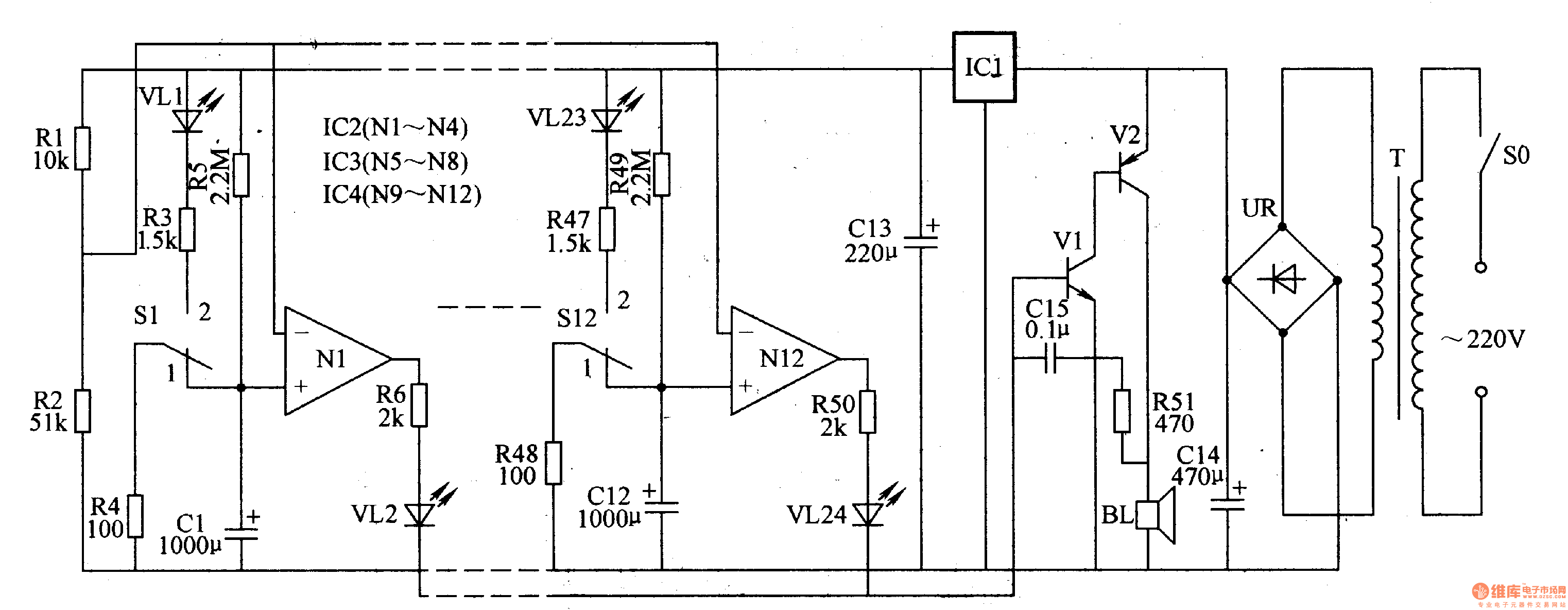
Circuit Operation Principle The medical automatic timing blood sedimentation circuit consists of a power supply circuit, an audible alarm circuit and a timing circuit, as shown in Figure 9-158.

The power circuit is composed of a power switch SO, a power transformer T, a rectifier bridge stack UR, a filter capacitor C13, C14, and a three-terminal voltage regulator integrated circuit IC1.
The audible alarm circuit is composed of transistors V1, V2, a resistor R51, a capacitor C13, and a speaker BL.
The timing circuit consists of resistors Rl-R5O, capacitors Cl-Cl2, LEDs VL1-VL24, microswitches Sl-Sl2 and operational amplifier integrated circuits IC2 (Nl-N4), IC3 (N5-N8), IC4 (N9-Nl2) )composition. In order to simplify the circuit, only two timing circuits (12 channels in total) are shown, and R7-R46, C2-C11, VL3-VL22, S2-S11 and N2-NlI are not shown.
AC 220V voltage after T step-down, UR rectification, C14 filtering and ICl voltage regulation, one channel provides +I2V working voltage for IC2-1C4, one channel provides voltage reference for Nl-Nl2 inverting input terminal after Rl and R2 voltage division .
Usually (when the blood sedimentation tube is not installed on the blood sedimentation rack), the normally closed contact of S1-S12 is turned on, the normally open contact is disconnected, Nl-N10 outputs low level, and VLl-VL24 does not emit light, by Vl and V2 The audio oscillator of the composition does not work, and the BL does not sound.
When a tube position is fitted with a blood sedimentation tube, the normally open contact of the micro switch in the circuit timing circuit is turned on, the normally closed contact is opened, the green light emitting diode is turned on, the capacitor starts to be charged, and an operational amplifier output is performed one hour later. High level, the red LED lights up, Vl turns on, the audio oscillator oscillates, and the BL sounds an alarm.
For example, when the immersion tube is installed in the No. 1 tube position, the normally open contact of Sl is turned on, and the common contact is disconnected to make VLl light; meanwhile, Cl is slowly charged through R3, VLl and R5, when Cl is charged ( When lh), Nl outputs a high level due to the high-voltage of the positive phase input being higher than the voltage of the inverting input terminal, so that VL2 is lit, and the BL sounds an alarm to remind the laboratory personnel that the first stage of the blood immersion tube is finished at the timing, and should be timely. Observe its reading.
Component selection
Rl-R5l selects 1/4W metal film resistor for use.
Cl-C13 selects aluminum electrolytic capacitors with a withstand voltage of 16V; Cl4 uses aluminum electrolytic capacitors with a withstand voltage of 25V; Cl5 uses monolithic capacitors.
VLl-VL24 selects high brightness LED of φ3mm. VLl, VL3, VL5, VL7, VL9, VLll, VL13, VL15, VL17, VL19, VL21 and VL23 are selected in green, and the remaining LEDs are selected in red.
UR selects the rectifier bridge stack of lA and 5OV.
V1 selects S9013 or 3DG6 type silicon NPN transistor for use; V2 selects 3AX31 type é”—PNP transistor for use.
ICl selects LM7812 type three-terminal regulator integrated circuit for use; IC2-1C4 selects LM324 type four operational amplifier integrated circuit.
BL uses 0.25W, 8Ω miniature electric speakers.
T selects 3-5W, the secondary voltage is 13-15V power transformer.
S0 selects SA, 220V power switch; S1-S12 selects small micro switch.
KNBL1-32 Residual Current Circuit Breaker With Over Load Protection
KNBL1-32 TWO FUNCTION : MCB AND RCCB FUNCTIONS
leakage breaker is suitable for the leakage protection of the line of AC 50/60Hz, rated voltage single phase 240V, rated current up to 63A. When there is human electricity shock or if the leakage current of the line exceeds the prescribed value, it will automatically cut off the power within 0.1s to protect human safety and prevent the accident due to the current leakage.
leakage breaker can protect against overload and short-circuit. It can be used to protect the line from being overloaded and short-circuited as wellas infrequent changeover of the line in normal situation. It complies with standard of IEC/EN61009-1 and GB16917.1.
KNBL1-32 Residual Current Circuit Breaker,Residual Current Circuit Breaker with Over Load Protection 1p,Residual Current Circuit Breaker with Over Load Protection 2p
Wenzhou Korlen Electric Appliances Co., Ltd. , https://www.zjmannualmotorstarter.com