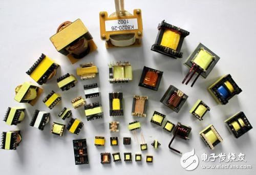
"Switching transformer" generally refers to the transformer used in "switching power supply". When working in a pulse state of a frequency of ten to several tens of kilohertz or even hundreds of kilohertz, the iron core is generally made of ferrite material. The switching power supply transformer is a power transformer with a switching tube. In addition to the voltage conversion function of the ordinary transformer, the circuit also has the functions of insulation isolation and power transmission, which are generally used in switching power supplies and the like involving high frequency circuits.
Switching transformer
The switching power supply transformer and the switching tube together form a self-excited (or other) intermittent oscillator that modulates the input DC voltage into a high frequency pulse voltage.
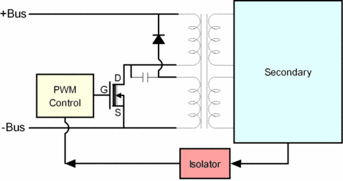
It plays the role of energy transfer and conversion. In the flyback circuit, when the switch is turned on, the transformer converts the electric energy into a magnetic field and can be stored, and is released when the switch is turned off. In a forward circuit, when the switch is turned on, the input voltage is directly supplied to the load and the energy is stored in the storage inductor. When the switch tube is turned off, the energy storage inductor performs a freewheeling flow to the load.
Convert the input DC voltage to the various low voltages required.
Switching transformer working principle
For switching power supplies, the working principle of switching transformers is different from that of ordinary transformers. The positive and negative half-cycle waveforms of the AC voltage or current input by the ordinary transformer are all symmetrical, and the input voltage and current waveforms are generally continuous. Within one cycle, the average value of the input voltage and current is equal to 0. This is common. The basic characteristics of the working principle of the transformer; while the switching transformer generally works in the switching state, its input voltage or current is generally not continuous, but intermittent, the average value of the input voltage or current within a period is mostly Not equal to 0, therefore, the switching transformer is also called pulse transformer, which is the biggest difference between the working principle of the switching transformer and the ordinary transformer.
In addition, the switching transformer has a single-excitation and double-excitation type for the input voltage: for the output voltage, there are both forward and flyback. Single-excitation and double-excited switching power supplies, or forward- and reverse-excited switching power supplies, use switching transformers that vary greatly in their operating principles.
When the input voltage of the switching transformer is DC pulse voltage, it is called unipolar pulse input. The switching power supply of this unipolar pulse input is called single-excited transformer switching power supply: when the input voltage of the switching transformer is positive and negative alternate The pulse voltage is called bipolar pulse input. This bipolar pulse input switching power supply is called double-excited transformer switching power supply; when the primary coil of the transformer is being excited by DC pulse voltage, the secondary winding of the transformer There is just power output. This kind of switching power supply is called forward transformer switching power supply. When the primary coil of the transformer is excited by DC pulse voltage, the secondary coil of the transformer does not provide power output to the load, but only in the primary coil of the transformer. The excitation voltage is turned off to provide power output to the load. This transformer switching power supply is called a flyback switching power supply.
Let the cross section of the switching transformer core be S. When a rectangular pulse voltage of amplitude U and width τ is applied to the primary coil of the switching transformer, an excitation current flows in the primary coil of the switching transformer: at the same time, at the switch A magnetic field is generated in the iron core of the transformer, and the iron core of the transformer is magnetized. Under the action of the magnetic field with the magnetic field strength H, magnetic flux with magnetic induction intensity B is generated, which is referred to as magnetic flux, and is represented by "": magnetic induction The process in which the intensity B or the magnetic flux φ is changed by the magnetic field strength H is called a magnetization process. The so-called excitation current is the current that magnetizes and demagnetizes the transformer core.
According to the Faraday's electromagnetic induction theorem, when the magnetic field or magnetic induction in the inductor changes, an induced electromotive force is generated in the coil: the induced electromotive force in the coil is:
U=NdΦ/dt=NSdB/dt(2-4)
Where N is the number of turns of the primary coil of the switching transformer: Φ = SB is the magnetic flux of the transformer core; B is the average of the magnetic induction or magnetic induction of the transformer core.
The concept of the average value of the magnetic induction is introduced here because the magnetic flux in the transformer core is not uniformly distributed, and the magnetic induction is related to the actual distribution of the magnetic flux on the core or core cross section. Therefore, when analyzing certain macroscopic characteristics such as transformers, it is sometimes necessary to use the concept of averages in order to deal with problems simply.
It can be seen from the equation (2-4) that when the change in the magnetic induction intensity is performed at a constant rate, it can be expressed as follows:
dB/dt=Ut/NS(2-5)
Assume that the initial value of the magnetic induction is B(0)=B. (t=0), when t "0", the magnetic induction intensity increases linearly, and the magnetic induction intensity increases linearly, namely:
B=B. +Ut/NS(2-6)
When t=τ, that is, when the time reaches the trailing edge of the pulse, the magnetic induction reaches the maximum value Bm=B(τ) The magnetic induction intensity increment (the difference between the initial value and the final value of the magnetic induction) ΔB=B(τ)-B (0)=Bm-B0
When the input voltage is a sequence of unipolar rectangular pulses, according to the law of electromagnetic induction, a magnetic induction increment is generated in the transformer core, namely:
â–³B=UÏ„/NS(2-7)
If the influence of the eddy current can be ignored, the average value of the magnetic field strength H depends on the nature of the magnetizing material. The increase in magnetizing current in the primary coil of the transformer is proportional to H. The magnetic field strength H, the magnetizing current, and the magnetic induction B in the straight line segment of the characteristic curve all vary linearly.
After the end of the pulse voltage (t Ï„), the magnetizing current in the transformer will decrease according to the output circuit characteristics of the transformer, that is, the law determined by the circuit parameters, and the magnetic field strength and magnetic induction intensity in the transformer core are also correspondingly weakened. A reverse polarity voltage, ie, a counter electromotive force, is generated in the transformer coil.
Although the above analysis takes the unipolar pulse input as an example, it is also effective for the bipolar pulse input: in the method, it is only necessary to treat the bipolar pulse input as two unipolar pulses respectively.
Switching transformers are divided into single-excited switching transformers and double-excited switching transformers. The working principle and structure of the two switching transformers are not exactly the same. The input voltage of a single-excited switching transformer is a unipolar pulse, and is also divided into a positive flyback voltage output: the input voltage of the double-excited switching transformer is a bipolar pulse, which is generally a bipolar pulse voltage output.
In addition, in order to prevent magnetic saturation, the air gap is generally left in the core of the single-excited switching transformer; while the magnetic induction intensity variation range of the double-excited switching transformer is relatively large, and magnetic saturation is generally not easy to occur. Therefore, generally do not use gas-extended single-switching transformers, which are divided into two types: forward and flyback. The technical parameters of the two types of switching transformers are different: the comparison of the primary inductance requirements of the forward switching transformer Large, and the primary inductance of the flyback switching transformer, the size is also related to the output power.
The hysteresis loss of the double-excited switching transformer core is relatively large, while the hysteresis loss of the single-excited switching transformer core is relatively small. These parameters are basically related to the magnetization curve of the transformer core.
ShenZhen Antenk Electronics Co,Ltd , https://www.antenkwire.com