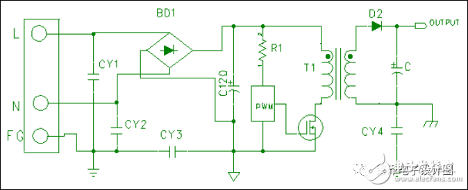
Basic schematic diagram of switching power supply

1. Primary circuit: Directly connected to the external grid power supply.
2, secondary circuit (Secondary Circuit):
The part of the circuit that is isolated from the primary side of the device.
3. Y-capacitor: A high-voltage capacitor that is connected between a circuit and ground or a secondary circuit.
Switching power supply grounding, leakage current, withstand voltage test (safety)
1. Ground Continuity Test:
A. Definition: From the Inlet PG end through the current to the user can touch the ground, to ensure that its resistance is less than the specification value, to achieve the function of grounding protection.
B. Standard: B.1 Input current is not more than 25A, (DC or AC) voltage does not exceed 12V, time is at least 3 seconds (TUV requirement). B.2 Test result: Resistance value should not exceed 100 mΩ.
2. Earth Leakage Current Test:
A. Definition:
Through a "body impedance analog circuit" approved by the safety unit (UL, TUV, CSA...), measuring the flow of the object to be tested (SPS) between the accessible metal parts and the ground when the device (SPS) is powered on Electricity flow.
B. Standard Huai:
B.1 The input voltage is 106% of the upper rated voltage. B.2 Test result: Class I≦3.5mA; Class II≦0.25mA.
3. Dielectric Withstand Voltage Test:
A. Definition: Also known as high-voltage dielectric test, Hi-pot (High Potential) Test, high voltage is applied from the primary side to the secondary side (or primary side to ground) to determine the isolation voltage of the internal insulation layer. The function.
B. Standard: B.1 The input voltage is as follows:

B.2 Test results: There is no insulation breakdown (Breakdown).
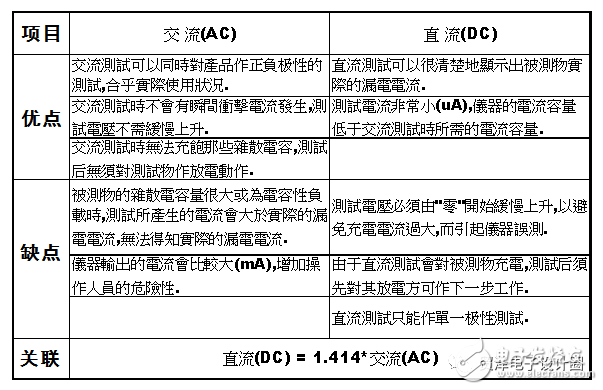
The difference between the withstand voltage test AC and DC

Calculation method of leakage current in withstand voltage test
1. DC test leakage current setting: DC test current is very small (μA), generally DC high voltage is applied between the primary side and the secondary side, and the leakage current is set: 0μA~100μA.
2. Theoretical calculation of leakage current in AC test:
Calculation formula: I = 2Ï€ * f * V * Cy
Where f - test voltage frequency (50Hz or 60Hz) V - test voltage (unit: volt)Cy - the sum of the Y capacitances between the primary side and the ground or between the primary and secondary sides.
Therefore: Imin = 2Ï€ * f * V * CyminImax = 2Ï€ * f * V * CymaxCy Capacitance calculation: Cy = Cy1 + Cy2+Cy3 +...
If a Y capacitor (Cy0) is connected between the primary side ground and the secondary side ground, then

Y capacitor tolerance is generally: +/-20% OR +/-10%
3. The following factors should be considered when actually setting the AC test leakage current:
(1). Consider the initial leakage current: the initial leakage current is the measured leakage current in the state without the object to be tested.
(2). Consider Y capacitance tolerance: When the power supply engineer selects the Y capacitor of the same capacity, there are often several models, but the tolerances are different (some are +/-10%; some are +/-20%), give The actual leakage current setting is troublesome, so we should set it by +/-20% tolerance. Otherwise it must be set according to +/-10% tolerance.
(3). Consider the distributed capacitance existing in the actual line, so the leakage current range is set: (lower limit is rounded: upper limit is rounded)
Recommended reading article:A face is arrogant! Is the LED driver power supply constant current? Or constant voltage power supply?
I have a trick! No longer afraid that the microcontroller and digital circuits are disturbed.....
How to configure CRC parameters in IAR? It’s too detailed!
It is too practical! Various component stress derating quick checklist, take away!
Want to place RF circuits and digital circuits on the PCB? Poke in hard
Enhance industrial motor control performance with digital isolator technology
Have you mastered the microcontroller I/O driver and isolation circuit design?
Daniel has something to say: How to use digital isolator technology to enhance industrial motor control performance?
Is the component really difficult to distinguish? Siege lions should have eye-catching eyes
Is the tantalum capacitor burned? explosion? The reason is actually this...
About the microcontroller, ARM, FPGA, embedded things you don't know.....
How to properly apply EDA software in circuit design? Just look at this!
About the Moser Electronic Design CircleThe Moser Electronics Design Circle is developed and operated by Mouser Electronics to serve the global electronics design community. The company distributes more than 600 leading brands and can order more than 4 million online products for design engineers and procurement personnel. Provide one-stop shopping platform, welcome to pay attention to us, get first-hand design and industry information!
Heat shrinkable tube is a special heat shrinkable tube made of polyolefin.
The outer layer is made of high quality soft crosslinked polyolefin material and the inner layer of hot melt adhesive.
The outer layer has the characteristics of insulation, corrosion resistance and wear resistance, and the inner layer has the advantages of low melting point, waterproof sealing and high adhesion.
Low Voltage Heat Shrinkable Adhesive Tape has excellent flame retardancy, environmental protection, insulation, flexibility, stable performance, low shrinkage temperature and fast shrinkage.
We are the professional manufacturer of Electrical Tapes ,Insulating Tape and Special Adhesive in China for more than 25 years,if you want to know more information about our company and products, please visit our website.
We are the professional manufacturer of Rigid Heat Shrink Tubing(Rigid Heat Shrink Tubing) in China for more than 25 years,if you want to know more information about our company and products, please visit our website.
Composite Heat Shrink Tubing,Shrink Tape For Carbon Fiber,Shrink Tube For Wires,Waterproof Heat ShrinkBusbar Heat Shrink Tubing,Busbar Heat Shrink Sleeve,Busbar Heat Shrink,Heat Shrink Busbar Insulation
CAS Applied Chemistry Materials Co.,Ltd. , https://www.casac1997.com