The oscilloscope is an indispensable tool for measuring power supply ripple and power supply noise, but in actual measurement, how to choose the appropriate bandwidth, sampling rate, how to choose the probe, oscilloscope coupling, and even grounding will bring different results to the measurement results. The following summarizes some of the key considerations from specific practical cases.
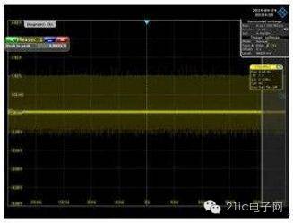
Definition of Power Ripple and Power Noise
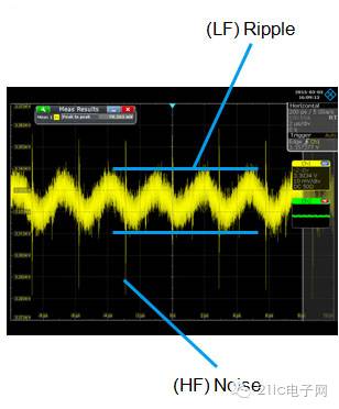
Currently, there is no standard definition for power supply ripple and power supply noise. However, the industry has gradually formed a convention that understands the power supply ripple as the fluctuation of the output voltage of the power module including the VRM, regardless of the complex power supply network, or the voltage fluctuation of the source end (Source) of the power supply output. The power supply noise refers to the power module working in the actual product system. The power supply is transmitted to the chip pin through the power distribution network, the voltage fluctuation at the chip pin, or simply the end of the power output (Sink end) ) The fluctuation of the voltage.
It can also be said that the fluctuation of the voltage is called Ripple at the source end and noise (Noise) at the end.
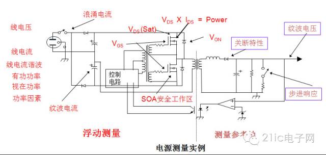
First, the oscilloscope bandwidth selection
Bandwidth is the most important indicator of an oscilloscope. In theory, as long as the bandwidth covers 99.9% of the measured signal energy, the measured error can be less than 3%, which is the appropriate bandwidth. Therefore, the industry also has multiple bandwidth selection rules, such as: 5 times rule, triple sine wave frequency, 1.8 times rule, 1/3 rule. Different rules apply to different measurement signals and measurement requirements.
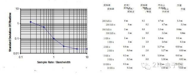
Based on the relationship between rise time and bandwidth, it seems to be concluded that the higher the bandwidth, the smaller the measurement error. But in fact, this is not the case in specific applications. Because the oscilloscope is not an ideal instrument after all, the measurement system itself is noisy. These noises include the noise of the amplifier, the noise of the ADC, the noise of the active probe, the spatial radiated noise induced by the ground of the probe, and the conducted noise of the ground loop coupling. From the perspective of signal-to-noise ratio, only when the energy of the measured signal is much larger than When the oscilloscope measures the noise energy brought by the system itself, that is, when the signal-to-noise ratio is large enough, the selected bandwidth is suitable. The bandwidth selection of the power ripple measurement depends on the rise time of the power switch tube, and the bandwidth of the measured ripple is equal to the bandwidth of the measurement switch. The power switching frequency of a small power can reach 1MHz or even larger, and the rise time of the corresponding switching tube is smaller. The power switch with high power has a small switching frequency, only 100KHz or less, and the rise time is large. However, most switching transistor MOSFETs have a rise time of 100ns. Even if the rise time of the switch is only 30ns, the rise time of 1/3 is 10ns, and the rise time of the 100MHz oscilloscope is only 3.5ns. Therefore, it is sufficient to measure the switching tube of the switching power supply with a 100MHz bandwidth oscilloscope. In fact, there are very few switch tube rise times of only 30ns, and limiting the bandwidth to 20MHz is sufficient. This is what many people call "the need to limit the oscilloscope bandwidth to 20MHz when measuring power supply ripple." Of course, some switches require higher bandwidth. For example, the new CoolMOS rise time is 11ns and the fall time is 3ns, and the bandwidth requires at least 300MHz. Second, the measurement of the sampling rate of the power supply ripple selection In general, according to the sampling rate required to measure the switch tube can be selected, for most MOS tubes, according to 250MS / s is sufficient. Remember: The sampling rate is chosen to test the rising edge of the waveform detail of interest to sample 3-5 points, preferably more than 5 points. Of course, the high sampling rate reduces the distortion of the test waveform.
Third, the capture time required to measure the power supply ripple
The power supply ripple based on the AC input of the 220V grid includes the switching frequency and the power frequency component; the power frequency component is the 100 Hz signal after rectification. It takes 20ms to capture two full 100Hz cycles, so the recommended time base is set to 2ms/div or more.
Please keep in mind: storage depth = sampling rate * sampling time
In the case of a certain storage depth, the faster the storage speed, the shorter the storage time, and there is an inverse relationship between them.
Increasing the storage depth of the oscilloscope can indirectly increase the sampling rate of the oscilloscope: when the waveform is to be measured for a long time, since the storage depth is fixed, the sampling rate can only be reduced to achieve, but this will inevitably lead to a decrease in the quality of the waveform; Large memory depths can be measured at higher sample rates to obtain undistorted waveforms. Fourth, the oscilloscope bottom noise required for measurement is as small as possible
The noise floor indicates the baseline amplitude of the oscilloscope without any signal input. The user simply looks at the thickness of the baseline with the naked eye, or measures the Pk-Pk, SDEV or RMS values ​​of the baseline.
As a standard test equipment, if the oscilloscope's own noise floor is large, it is difficult to measure the true condition of the signal under test.
If the noise floor of the measurement system consisting of an oscilloscope and a probe is close to or greater than the measured supply ripple/power supply noise, that is, the measured signal-to-noise ratio (SNR) is too small, the power supply ripple/power supply noise is overwhelmed by the oscilloscope's local noise. Fifth, the oscilloscope detection method â— 10:1 probe attenuation circuit caused by the noise floor amplification 10 times
The input impedance of the oscilloscope and the impedance of the probe form an attenuator circuit. The oscilloscope automatically detects the attenuation ratio of the probe and re-adjusts the oscilloscope's vertical range setting to reflect the attenuation of the probe. Using a 10:1 probe means that the oscilloscope's current vertical range setting is 10 times the oscilloscope's internal amplifier input. The signal is attenuated, but the noise is not attenuated. The software amplifies the attenuated signal by a factor of 10 and the noise by a factor of 10.
Therefore, when the detection mode is selected, it will have different effects on the test result. It is a 10:1 passive probe or a 1:1 passive probe or a 1:1 coaxial cable, which needs to be determined according to its actual situation. â— 1:1 coaxial cable is necessary for weak power supply ripple/noise measurement. Using a probe with an excessive attenuation factor can also result in the inability to set the oscilloscope's vertical sensitivity to a minimum, resulting in greater quantization error. If a conventional passive probe or active probe is used, the minimum gear can only be 10mV/div or 20mv/div due to the attenuation factor of 10:1. In the 20mV gear position, the noise floor is usually greater than 30mV. It is impossible to accurately test the voltage of 1.8/2.5. When the voltage is 20mV, the offset voltage of the probe can be adjusted to a small extent. If DC coupling is used, some voltage may not be measured. Sixth, the coupling mode of the oscilloscope â— AC 1M Europe or DC 50 Euro + DC blocking capacitor? The power and ground impedance at the chip end is usually milliohm level. After the high frequency power supply noise is transmitted from the coaxial cable to the oscilloscope channel, when the oscilloscope input impedance is 50 ohms, the characteristic impedance of the coaxial cable is 50 ohms and the channel is completely Matching, no reflection; and when the channel input impedance is 1M ohm, it is equivalent to high resistance. According to the transmission line theory, the power supply noise is reflected. Thus, the power supply noise tested at 1M ohm input impedance is higher than 50 ohms.
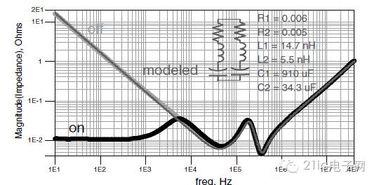
â—Load effect
When the probe is connected to the circuit, it takes energy from the circuit and sends it to the oscilloscope. A probe is a "circuit network" that is an additional "load" that a signal source must drive.
The left side of the red line on the right shows the circuit to be tested. When the probe on the right side of the red line is connected, the probe absorbs current from the signal source. The circuit network of this probe includes resistors, inductors and capacitors.
If the probe impedance is much larger than the impedance of the circuit under test (typically 50 ohms for high-speed circuits), the circuit absorbed by the probe is very small. If the impedance of the probe is equal to the impedance of the circuit, the current drawn from the circuit under test and the circuit under test are flowing. The current is the same.
If the probe absorbs too much current from the circuit under test, the circuit under test will malfunction or even stop normal. Usually, the circuit under test still looks to work normally. However, since the current is absorbed, the measured signal voltage drops, which will affect the user's judgment on the true condition of the circuit under test. If the probe is not well recognized. The effect of the load effect.
Is the oscilloscope set to DC or AC?
The only reason to set the AC coupling is that in the case of DC coupling, some oscilloscopes have insufficient bias voltage ranges when the range is only 2mv/div or even smaller.
â— How big is the DC blocking capacitor?
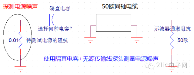
The circuit consisting of a DC blocking capacitor and an oscilloscope's 50 ohm resistor is a bandpass filter. At low frequencies, the equivalent series inductance ESL of the capacitor can be ignored. The DC blocking resistor and the 50 ohm resistor of the oscilloscope channel form an RC circuit. The 3dB cutoff frequency is, as the frequency increases, the ESL of the capacitor and the parasitic inductance in the probe become more and more important. The inductance of the inductor increases with the increase of frequency, and the high frequency 3dB cutoff frequency and probe and capacitor The parasitic inductance is related.
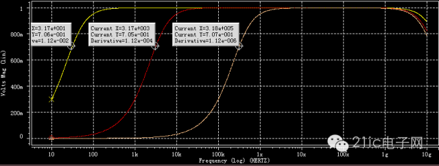

It is recommended to use a DC blocking capacitor of 1 uf or more. 7. Grounding In the test, regarding the grounding of the oscilloscope, one principle to keep in mind is that “the shorter the ground wire, the better.†The engineer can ensure that the ground wire is as short as possible by the following methods during configuration: ◠Reduce the loop between the probes. ◠Place the probe in the proper position. ◠The cable of the probe is as far away as possible from the radiation source. ◠The cable of the probe avoids entanglement to avoid loops between itself and pick up more space radiation noise.
â— For differential probes, try to couple the positive and negative cables of the probe together so that the positive and negative cables of the probe are subjected to balanced space radiation to facilitate the elimination of common mode noise.
8.4V Charger,8.4V Li-Ion Battery Charger,Battery Charger For Drone,Li Ion Battery Charger
ShenZhen Yinghuiyuan Electronics Co.,Ltd , https://www.yhypoweradapter.com