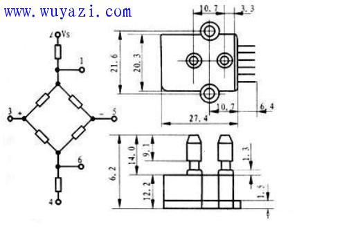
The BP01 pressure sensor is specifically designed to monitor blood pressure and is primarily used in portable electronic sphygmomanometers. It is made of precision thick-film ceramic chip and nylon plastic package, featuring high linearity, low noise and low external stress. It uses internal calibration and temperature compensation to improve measurement accuracy, stability and repeatability at full scale. Within the range, the accuracy is ±1% and the zero offset is no more than ±300μV. 
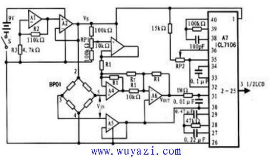
Working principle: The principle circuit of the portable electronic sphygmomanometer composed of BP01 is shown in the figure. It consists of bias power supply circuit (A1, A2), pre-processing circuit (A3~A6), display circuit (A7) and pressure sensor ( BP01) consists of a blood pressure measuring range of 0 to 200 mmHg and a resolution of 0.1 mmHg. The working power supply is a 9V laminated battery. The working principle of each main circuit in the sphygmomanometer is described as follows: 
Bias power supply circuit: The power supply circuit is composed of a dual op amp LM10 with a built-in reference voltage. A1 constitutes a non-inverting amplifier, and A2 constitutes a follower. Their function is to amplify the built-in reference voltage and use it as the bias voltage of the pressure sensor BP01. Vs, the value of Vs is determined by: Vs = Vref (1 + R2 / R3) where: Vref is the built-in reference voltage of LM10. The value is 200 mV, and this value is substituted into the above equation together with the values ​​of R2 and R3 in the circuit to obtain a value of the bias voltage Vs of 5V.
Pre-processing circuit: The pre-processing circuit is composed of four operational amplifiers A3~A6, wherein A3 constitutes an offset bias circuit to compensate for circuit offset; A5 constitutes a follower for isolating buffer of the output signal of pressure sensor BP01 A4 and A6 form an amplifying circuit whose gain AV is determined by the following equation: AV=1+(R1/RT). If the offset is ignored, the output voltage Vout of the pre-processing circuit is: Vout=2(1+R1/RT)VIN Medium: VIN is the output voltage of the pressure sensor BP01.
Display circuit: The display circuit uses three and a half display drivers. During operation, the output of the pressure sensor BP01 is amplified by the pre-processing circuit, and the LCD is driven by the display drive circuit to read the measured blood pressure value.
Debugging method: Zero-voltage output adjustment When the zero-voltage output is adjusted, the offset potentiometer RP1 is adjusted. When the displayed value of the sphygmomanometer is 000.0, the zero-pressure output adjustment is considered complete.
Pressure Gauge,Manometer Pressure Gauge,Automobile Pressure Gauge,High-Quality Pressure Gauges
ZHOUSHAN JIAERLING METER CO.,LTD , https://www.zsjrlmeter.com