1 Add the light painting layer manually
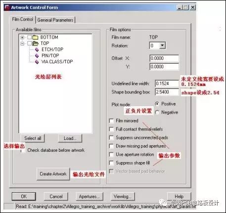
The command for output light painting is under the menu Manufacture=>Artwork or click the icon in the toolbar, the opened window is as follows:

The above picture is the layer control window for light painting output, and another window is the control window for output parameters. We open this window by clicking the second list item General Parameters in the above picture. The opened window is as follows. Note that the output format is RS274X .

There are two default output light drawing layer lists in Allegro software: TOP and BOTTOM. We need to add them according to the corresponding layer. Take a four-layer board as an example. When there are no components on the bottom layer, 8 light drawing files (actual It is 7 films, the drilling is not counted by the PCB processor), the eight gerber files from top to bottom are:
l Top silk screen (Topsilk)
l Top mask (Topmask)
l Top layer routing (Top)
lGND layer (Gnd)
lVCC layer (Vcc)
l Bottom
l Botmask
l Drilling layer (Drill)
If the components are placed on the bottom layer, a layer of bottom silk screen (Botsilk) is also needed. According to the above description, I believe that everyone has a certain understanding of how to calculate the number of gerber files output. The following is for this board. Explain the relevant layers that need to be opened during output:
1. Top silk screen (Topsilk)
lREF DES/SILKSCREEN_TOP
lPACKAGE GEOMETRY/SILKSCREEN_TOP
lBOARD GEOMETRY/OUTLINE
2. Top mask
lVIA CLASS/SOLDERMASK_TOP
lPIN/SOLDERMASK_TOP
lPACKAGE GEOMETRY/SOLDERMASK_TOP
3. Top layer routing (Top)
lETCH/TOP
lPIN/TOP
lVIA CLASS/TOP
4. GND layer (Gnd)
lETCH/GND
lPIN/GND
lVIA CLASS/GND
5. VCC layer (Vcc)
lETCH/VCC
lPIN/VCC
lVIA CLASS/VCC
6. Bottom
lETCH/BOTTOM
lPIN/BOTTOM
lVIA CLASS/BOTTOM
7. Botmask
lVIA CLASS/SOLDERMASK_BOTTOM
lPIN/SOLDERMASK_BOTTOM
lPACKAGE GEOMETRY/SOLDERMASK_BOTTOM
8. Drilling layer (Drill)
lMANUFACTURING/NCDRILL_LEGEND
lMANUFACTURING/NCDRILL_FIGURE
lBOARD GEOMETRY/OUTLINE
lBOARD GEOMETRY/DIMENSION
Below we refer to the above list to set up the light painting of each layer, the specific operation steps are as follows:
1. Run the command Manufacture=>Artwork or click the icon on the toolbar.
2. Right-click the "TOP" character in the gerber output list, and select the Add command in the pop-up menu.
3. Enter "Topsilk" in the pop-up window and press the OK button to close the window (add top silkscreen)
4. Click the "+" sign on the front end of the Topsilk layer to open the list items as shown below:

5. Use the "Cut" and "Add" commands of the right-click menu to delete useless layers, and add layers related to silk screen printing, namely REF DES/SILKSCREEN_TOP, PACKAGE GEOMETRY/SILKSCREEN_TOP and BOARD GEOMETRY/OUTLINE
6. Use the same method to set up the other layers of light painting. Refer to the list above for related layers.
7. Set the Undefined line width of all layers to 0.1524
8. Set the shape bounding box of all layers to 2.54
9. Set the GND and VCC layers to negative, and select Negative in Plot mode
10. Select the bottom output parameter Vector based pad behavior
11. Set the parameters of General Parameters as shown in Figure 3.20
12. Click the OK button to close the Artwork Control Form window
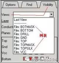
At this time, we look at the views option in the Visibility parameter on the right, and we can see the light drawing output layer list as shown in the following figure:

In fact, the output of the light painting should be set before routing, so that in the future routing process or other processes, you can quickly switch related layers through the views list under the Visibility parameter on the right of Allegro, for example, I want to route the wires on the Bottom layer, and I want to close the display of other layers. At this time, we can select Bottom in the views list, and all other layers will be closed, leaving only the Bottom layer.
2 Output Gerber File
Then you can output the gerbera file, check the parameter settings, if the parameters are OK, click the "Select all" button to select all layers, and then click the "Create Artwork" button to start the gerbera output, the generated gerbera file The extension is "art", and the files are stored in the physical directory. We compress these ART files, drill holes ncdrill1.tap and nctape.log files into RAR (compression software) files, and use this compressed RAR file. PCB processing is ready.
After exporting the gerbera file, it is recommended that you use Cam350 and other software that specializes in editing and viewing the gerbera file to check to see if the output gerbera file has errors.
Mobile phones and earphones have become necessities in our lives. How many people feel restless when they don`t have a mobile phone around. The mobile phone gives us a great sense of security to a certain extent, and its additional earphones also have such a function. . Wear headphones when you don`t want to talk; when you don`t want to listen to others, you wear headphones; when you don`t want to be harassed in an unfamiliar environment, you can play your favorite songs, be happy or sad, and enjoy your little universe most comfortable. There are now a variety of earphones on the market for people to choose from. From the original wired earphones to the current wireless Bluetooth earphones, they are more and more in line with people's requirements, and the sound quality and noise reduction are also constantly improving.
If you want to get a sports headset (sports scene) or a true wireless tws true wireless Bluetooth headset, what you expect from him is that it has the ability to withstand the test of different environments, wear it steadily, and have a long battery life, or it may be out of the street. Appearance, excellent sound quality, stable connection, friends who have certain requirements for sound quality and low requirements for noise reduction. You can take a look our earbuds.
Tws Earphones,True Wireless Earphones,Good Sound Earbuds,Hifi Sound Headphones
Shenzhen Focras Technology Co.,Ltd , https://www.focrass.com