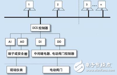
The control algorithm is rich, integrating continuous control, sequential control and batch control. It can realize advanced control such as cascade, feedforward, decoupling, adaptive and predictive control, and can easily add the special control algorithm required. The DCS is very flexible and can be composed of a dedicated management computer station, an operator station, an engineering station, a recording station, a field control station, and a data acquisition station. It can also be composed of a general-purpose server, an industrial control computer, and a programmable controller.
The process control level at the bottom layer generally implements data acquisition and control on-site by distributed field control stations, data acquisition stations, etc., and transmits them to the production monitoring level computer through the data communication network. The production monitoring level performs centralized operation management on data from the process control level, such as various optimization calculations, statistical reports, fault diagnosis, and display of alarms. With the development of computer technology, DCS can achieve more advanced centralized management functions such as scheduling, warehouse management, and energy management by connecting to higher-performance computer equipment as needed.
structure
Divided by structure, DCS includes process level, operation level and management level. The process level is mainly composed of process control stations, I/O units and field instruments, and is the main implementation part of the system control function. The operating level consists of an operator station and an engineering station to complete the operation and configuration of the system. The management level mainly refers to the factory management information system (MIS system). As a higher-level application of DCS, there are few systems applied to this layer in the domestic paper industry.
DCS control program: The control decision of the DCS is done by the process control station, so the control program is executed by the process control station.
The composition of the process control station:
The DCS process control station is a complete computer system consisting mainly of power supply, CPU (central processing unit), network interface and I/O.
I/O: The control system needs to establish the input and output channels of the signal. This is the I/O. I/O in DCS is generally modular, with one or more I/O channels on one I/O module for connecting sensors and actuators (regulators).
I/O unit: Typically, a process control station consists of several racks, each of which can hold a certain number of modules. The rack where the CPU is located is called the CPU unit. There can only be one CPU unit in the same process station. The other racks that only use the I/O modules are I/O units.
Application of DCS in wastewater treatment process
The original sewage treatment control system consists of SBR reaction tank PLC and on-site display instrument. Among them, the PLC has a long time of failure and the failure rate is obviously increased, so that the control is mainly done manually by the process personnel, and because the site environment is bad, the site The instrument is often corroded and unstable, which has affected the stable operation of the sewage treatment system. Finally, Zhejiang University Central Control JX300X DCS was selected to update the control system and replace the field transmitter.
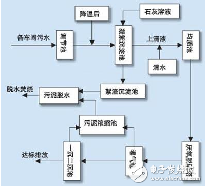
First, the processThe entire wastewater treatment process consists of the following five processes:
(1) Pretreatment process
The industrial sewage from each production workshop is discharged into the regulating tank. Because of the high water temperature, it is not conducive to the growth of fungi that decompose organic matter in the later process, and it needs to be naturally cooled before being discharged. A temperature node is set in the pool. When the water temperature drops to a set value, the valve is opened to allow the sewage to flow into the flocculation sedimentation tank. An electromagnetic flowmeter is installed in the waste water pipeline to complete the function of metering and settlement of the sewage.
The sedimentation tank periodically opens the lime pump and the valve, and adds the slaked lime solution according to the ratio control to strengthen the dewatering capacity of the sludge and improve the pH value of the sewage. The wastewater in the pool is collected offline in a few time periods, and the pH is measured. The scraper at the bottom of the sedimentation tank works regularly, and the precipitated sludge is scraped into the flocculation sedimentation tank, and the concentrated sludge discharged from the sludge is periodically controlled to enter the sludge dewatering process. The supernatant liquid in the sedimentation tank is diluted with water and discharged into the homogenization tank, and is discharged into the next process at regular intervals.
(2) Hydrolysis and acidification process
The main equipment for hydrolysis and acidification is four anaerobic desulfurization towers, which respectively receive the sewage raw liquid in four homogeneous pools, and each adds an electromagnetic flowmeter for cost settlement. The anaerobic bacteria cultured in the desulfurization tower can remove the BOD and COD of a part of the sewage liquid to achieve the purpose of sewage desulfurization treatment. According to the process requirements, the temperature in the tower is the most critical for the growth of anaerobic bacteria, and the temperature at the top of the tower and the temperature of the tower are used as reference quantities. Because the temperature of the steam valve is controlled to keep the temperature constant, and the steam flow disturbance has the greatest influence on the temperature, the temperature is controlled as the main control point in the tower, and the steam flow is controlled as the temperature-flow cascade control system of the secondary circuit, which ensures the tower. The internal temperature is stable. The desulfurized sewage is discharged into the SBR tank.
(3) SBR process
SBR is the abbreviation of Sequncing Batch Reactor AcTIvated Sludge Process, which is an activated sludge sewage treatment technology operated by intermittent aeration. The SBR reaction tank is the core of the entire sewage treatment plant. The macromolecular organic matter in the sewage is decomposed into small molecular organic matter, which is then decomposed into carbon dioxide and water. Therefore, the self-control of the SBR reaction tank is critical to the entire wastewater treatment system.
There is a large amount of activated sludge at the bottom of the SBR pool, and its main component is aerobic bacteria. Aerobic bacteria have a strong degradation effect on organic pollutants in sewage, and the number of their populations is directly related to the sewage treatment capacity of SBR pools. From the nitrification equation that has been carried out in the reaction tank: NH4++2O2→NO3-+2H++H2O+ energy
Only when there are enough oxygen molecules, the nitrification reaction can proceed normally, and the aerobic bacteria that degrade the organic matter can survive; but too much oxygen will cause a large amount of foam to be produced, the sedimentation performance of the sludge will decrease, and the energy consumption will increase, so the aeration of the SBR pool will be achieved. The control is the most critical. The ventilation is the timing control. When the deviation of the concentration of the dissolved oxygen meter in the line is too large, change the set value to adjust the duration of the intake air amount. The sewage feed valve and the mud discharge valve are also timing control. The SBR pool is equipped with an input level gauge control valve to prevent the overflow of sewage. The ultrasonic flowmeter is installed to measure the sewage, and the temperature node is heated to realize the constant temperature in the reaction tank.
(4) Contact oxidation process
The primary and secondary contact oxidation ponds in this process can be regarded as the continuation of the aeration tank. After sufficient oxidation, it is regularly discharged into the corresponding sedimentation tank, and the suspended solids such as sludge are removed by the principle of gravity sedimentation. Drive the suction machine to scrape the sludge into the sludge concentration tank. The treated water in the secondary settling tank has been sterilized by filtration and has met the national emission standards, and can be directly discharged or reused in the return water system.
(5) Sludge dewatering process
In the above process, the sludge is discharged into a concentration tank by a scraper to be dehydrated by a dehydrator to form a sludge cake having a low water content, which is sent to a rotary kiln for combustion, and finally discharged in the form of harmless carbon dioxide and water. The ash is buried deep.

Figure 1 Sewage treatment process flow chart
Second, the control system(1) Hardware configuration
The system consists of an engineering station, an operator station, an I/O station and a process control network, and is connected to the management computer of the workshop director via Ethernet to realize remote query remote control. The engineer software station is equipped with a configuration software platform to complete the task of modifying parameters and system maintenance; the operator station is the platform for the operator to complete the production process monitoring and management; the I/O station completes the implementation of the entire industrial process monitoring, by the main control card, data Forwarding card, I/O card, power supply unit, etc., in order to ensure the reliability of the system, the main control card and data forwarding card are redundant.
There are 2 SP243X main control cards; SP313 4 analog signal input cards 30; SP322 4 analog output cards 3; SP363 7 contact type switch input cards 8; SP364 7 relay output cards 10 One. There are a total of 108 AI signals; 8 AO signals; 40 DI signals; and 50 DO signals.
(2) Network structure

Figure 2 Sewage treatment system network structure
(three) software configuration
1. HMI
Display the general picture of the data, the history curve of each detection point, the process flow chart of each process, and the status of each valve in the field, and set different permissions to ensure the security of the system.
2. Report
At 8:30, 16:30, 0:30, the work report is in the form of: display the current point temperature and flow point data, flow accumulation, valve opening and closing time record, equipment running status; monthly monthly report In the form of daily record unit, showing the daily average value of the flow (the sum of the daily punctual records / 24), the monthly cumulative value, the daily average value of the temperature (the sum of the daily punctual records / 24), and can be input at the same time Other data is edited.
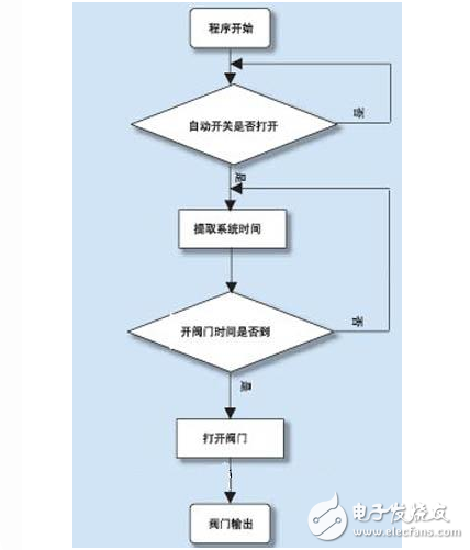
3. SBR reaction tank valve control: as shown in Figure 3.

Figure 3 valve control algorithm flow chart
4. SBR reaction tank valve status alarm:
If the valve in the aeration tank fails and is not discovered in time, the sewage will be discharged into the next process without sufficient degradation, and the national discharge standard of sewage purification cannot be achieved, resulting in a large loss, so the smart valve is used. The feedback signal is designed to valve the alarm program so that it can be processed in time after the failure to reduce losses.
The alarm is defined as: after the valve is opened/closed, no feedback signal is regarded as a valve failure within 12 seconds, and the sound and light alarm is used to remind the maintenance personnel to go to troubleshoot and resume production.
Third, the conclusionSince the introduction of the JX300X system in Zhejiang University, its stability and the friendly and rich control functions of the human-machine interface have been greatly improved compared with the original control system. It has been well received by the process personnel and self-control maintenance personnel to realize the sewage treatment system. The stability of operation and the improvement of the surrounding environment provide protection. However, some problems were also discovered during this period, with a view to further improving this when funds and post-maintenance measures were kept up. First, online analytical instruments are used sparingly. Only in the SBR reaction tank, there is dissolved oxygen on-line monitoring. The pH in the flocculation sedimentation tank is off-line analysis and the time lag is large, so it is only impossible to achieve self-control as a reference data.
If online analysis is implemented, the pH control of the pool can be controlled by controlling the opening and closing of the lime pump. In addition, a sludge concentration meter can be installed in the SBR reaction tank if conditions permit, so that the process personnel can more intuitively understand the growth of aerobic bacteria in the pool, and also provide for the determination of the amount of return sludge. Second, the decanter controller in the SBR reaction cell is a stand-alone control mode, which can only be operated according to a preset single working mode, if a fieldbus-based data connection is established between it and the DCS main control unit. To achieve data exchange, the decanter can be operated more flexibly according to different site environments and process requirements. Third, because the demand for dissolved oxygen in the SBR reaction tank is related to the life cycle of aerobic bacteria in the sludge, In the initial stage of treatment, the oxygen consumption is large, and then the situation is gradually reduced. It is not only the ability to find a suitable control algorithm for dissolved oxygen control, but also to replace the constant frequency fan with the variable frequency, which not only can better accomplish the sewage treatment task, but also It can reduce energy consumption, shorten processing cycles, and achieve optimal control.
We engineer loudspeaker solutions that offer great durability, quality sound, and peak performance. When an electrical signal is applied to the voice coil it generates a magnetic field. The voice coil and magnets within the Speaker interact causing the coil and attached cone to move, generating sound. Our loudspeakers incorporate large magnets and particular voice coils to handle a broad range of frequencies and sounds. Additionally, our loudspeakers can be configured in multiple cone materials, sizes, shapes and gaskets to adapt to different operational environments. We have provided loudspeaker solutions for both indoor and outdoor applications. Our loudspeaker designs can be found in home theater systems and on the handlebars of some of the most exquisite motorcycles.
Lond Speaker,Lead Wire Speaker,Waterproof Loudspeaker,Micro Waterproof Speaker
Jiangsu Huawha Electronices Co.,Ltd , https://www.hnbuzzer.com