1. There are two noises in the power amplifier: one is the hum noise that is caused by poor power supply filtering; the other is the interference noise introduced by the input shielding.
2. The noise caused by poor input shielding is relatively common. The noise is “shasha†and is controlled by the volume potentiometer. The identification method is: short circuit the ground with 4.7μ capacitor at the input end, it will disappear.
3. The AC interference sound caused by poor power supply filtering can increase the filter capacitor. The output power of LM386 is not large. Generally, 470μ electrolysis can be used.
Although the application of LM386 is very simple, but pay attention to it, especially when the device is powered on, power off, or even after the work is stable, some operations (such as plugging and unplugging the audio plug, rotating the volume control) will bring the transient impact. Very annoying noise is generated on the output horn.
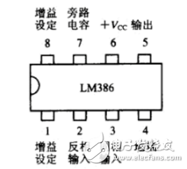
1. Change the gain by connecting the capacitor between 1 pin and 8 pin (1 pin capacitor + pole), and the gain is 20 when disconnected. Therefore, without using a large gain, the capacitor will not be connected, not only saves the cost, but also brings benefits - noise reduction, why not?
2. When designing the PCB, all peripheral components should be as close as possible to the LM386; the ground wire should be as thick as possible; the input audio signal path should be parallel as much as possible, and the output should be the same. This is dead, needless to say.
3. Select the potentiometer to adjust the volume. The quality is too bad, otherwise the victim is the ear; the resistance is not too big, 10K is the most suitable, too much will affect the sound quality, turn so many circles, do not bother that!

4. Use dual audio input/output whenever possible. The advantage is that the "+" and "-" outputs can cancel the common mode signal well, so it can effectively suppress common mode noise.
5. The bypass capacitor of the 7th pin (BYPASS) is indispensable! In practical applications, the BYPASS terminal must be connected with an electrolytic capacitor to the ground to filter out noise. After the operation is stable, the voltage of the pin is approximately equal to half of the power supply voltage. Increase the capacitance of this capacitor, slow down the rise and fall speed of the DC reference voltage, and effectively suppress noise. The noise when the device is powered on or off is caused by the instantaneous jump of the bias voltage. This capacitor can be saved!
6. Reduce the output coupling capacitance. This capacitor has two functions: blocking + coupling. Blocking the DC voltage, if the DC voltage is too large, it may damage the speaker coil; the AC signal of the coupled audio. It forms a first-order high-pass filter with the speaker load. Reducing the capacitance value makes the amplitude of the noise energy impact smaller and the width narrower; too low also increases the cutoff frequency (fc=1/(2Ï€*RL*Cout)). Tested separately, found that 10uF/4.7uF is the most suitable, this is my experience value.
7, the processing of the power supply is also critical. If there are multiple sets of power in the system, great! Due to different voltages, different loads, and different decoupling capacitors in parallel, the rise and fall times of each group of power supplies must be different. Very feasible method: put the power supply with short power-on and power-off time to +12V, choose the power supply with relatively slow rise as the Vs of LM386, but not lower than 4V, the effect is really very good!
Mini Solar Inverter,Solar Inverter System,Off Grid Solar Inverter,On Grid And Off Grid Inverter
Jinan Xinyuhua Energy Technology Co.,Ltd , https://www.xyhenergy.com