introduction
This paper designs a data recording device based on the actual needs of electric vehicle research. The data recording device is built on the battery energy management system and communicates with the energy management system to record the external state of the battery during actual operation of the electric vehicle (eg : battery voltage, current, temperature, etc.), on the one hand to study the working characteristics of the battery, on the other hand in order to verify the operation of the energy management system, to provide data support for the theoretical research of electric vehicle power battery.
1 overall system design
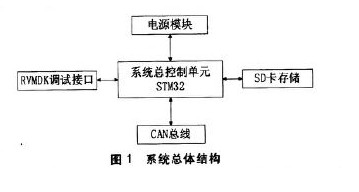
The design of the data recording device includes hardware design and software design. The software design mainly includes data receiving programming and data storage programming. The hardware design mainly has several aspects: the selection of the main control chip, the realization of the reset function, and the power supply. Modules, real-time clocks, communication modules, and SD card connections. The main control chip is the core of the control system. The more modules it integrates, the more external circuits can be saved, making the design of the circuit simpler and more convenient. Power modules are used to meet the different voltage requirements of various parts of the system. Real-time clock for accurate recording of system time stamps. The SD card is selected as a storage device to accommodate the massive data storage of the system. Based on the current market, the electric vehicle is mainly a CAN interface, so the device communicates with CAN. The overall structure of the system is shown in Figure 1.

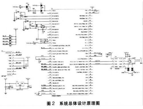
According to its actual function, the schematic diagram of the hardware part of the data recording device is shown in Figure 2.

2 hardware design
2.1 The main control chip selects the STM32F103RBT6 chip as the system controller. The STM32F103RBT6 is a high-performance, low-cost, low-power processor from STMicroelectronics. It uses the high-performance 32-bit RISC core ARMCortex-M3. The working frequency is 72MHz. Its price is lower, and the retail price is about 12 yuan.
2.2 reset function
The STM32F103RBT has two watchdogs built in. Two watchdog devices (independent watchdog and window 171 watchdog) can be used to detect and resolve faults caused by software errors, enabling software resets; when the counter reaches a given timeout value When an interrupt is triggered (for windowed watchdogs only) or a system reset is generated. The STM32 provides power-on reset and power-down reset, which provides the system with higher security, time accuracy and flexibility of use, making the program run more efficiently and the built-in reset function can meet the system reset requirements.
2.3 real time clock
The RTC real-time clock is built into the STM32F103RBT6, and the real-time clock is an independent timer. The RTC module has a set of counters that count continuously and provides the clock calendar function in the appropriate software configuration. Modify the value of the counter to reset the current time and date of the system. The RTC module and the clock configuration system (RCC-BDCR register) are in the backup area, ie the RTC settings and time remain unchanged after a system reset or wake-up from standby mode. After a system reset, access to the backing registers and RTC is disabled to prevent accidental writes to the backing area (BKP).
When the main power supply VDD is powered down, the VBAT pin is used to supply power to the real-time clock (RTC) and the backup register. The battery or other power supply is used to connect to the VBAT pin. When the VDD is powered off, the contents of the backup register and the function of maintaining the RTC can be saved. . The VBAT pin powers the RTC, LSE oscillator, and PCI3 to PCI5 terminals 13 to ensure that the RTC continues to operate when the main power is turned off. The switch that switches to the VBAT supply is controlled by the power-down reset function in the reset module.
2.4 power module
The power module provides power for the entire system. The STM32 microcontroller requires an operating voltage of 2.0-3.6V. The RTC part requires a battery to provide backup power. Here, the VBAT uses a CRl220 button battery and a VCC3.3V hybrid power supply, and has an external power supply (VCC3. At 3V), CRl220 does not supply power to VBAT. When the external power supply is disconnected, CRl220 supplies power to VBAT. Thus VBAT is always powered to ensure that the RTC's travel time and the contents of the backing registers are not lost. In terms of power supply of the single chip microcomputer, the AVSl7 voltage conversion chip of AMS is used to provide a working voltage of 3 3V for the single chip microcomputer. 

Active Stylus Pen,Stylus Pencil,Capacitive Stylus Pen,Tablet Pencil
Shenzhen Ruidian Technology CO., Ltd , https://www.wisonens.com