One, the principle of brushless motor
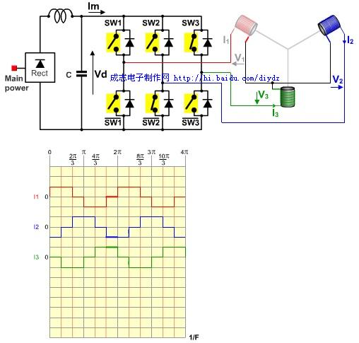
The following is the schematic diagram of the principle and control of the brushless DC motor in the previous issue (electric vehicle). In this issue, we focus on the operation principle of the brushless motor.

The positive power line of the Hall sensor inside the motor, that is, the red line, is generally connected to 5-12v DC. The majority is 5V.
The Hall's signal line transmits the position of the magnet in the motor relative to the coil. According to the three Hall's signal controllers, it can know how to supply power to the motor's coil at this time (different Hall signals should provide corresponding to the motor coil Direction of current), that is, the Hall state is different, and the current direction of the coil is different.
Second, the operating principle of the brushless motor
The Hall signal is transmitted to the controller. The controller supplies power to the motor coil through the motor phase wire (thick wire, not Hall wire), the motor rotates, the magnet and the coil (to be precise, the coil wound on the stator, in fact, Hall Generally installed on the stator) when the rotation occurs, the Hall senses a new position signal, the thick wire of the controller re-powers the motor coil to change the current direction, and the motor continues to rotate (when the position of the coil and the magnet changes, the coil must correspond Change the direction of the current, so that the motor can continue to move in one direction, otherwise the motor will swing around at a certain position instead of continuously rotating), which is electronic commutation.
as the picture shows
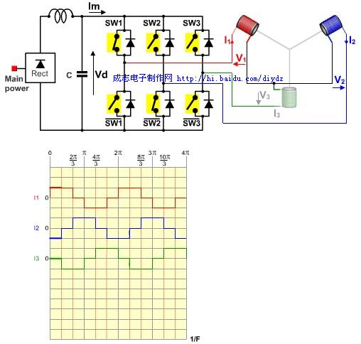
figure 1

figure 2
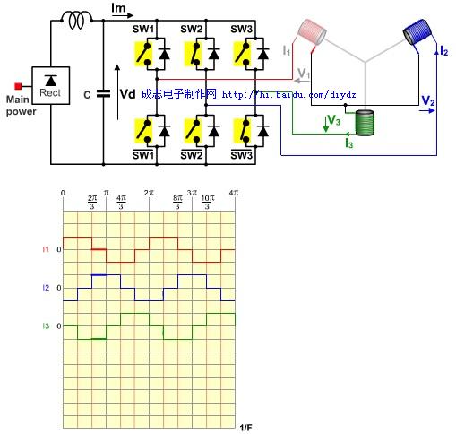
image 3
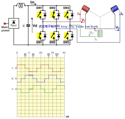
Figure 4
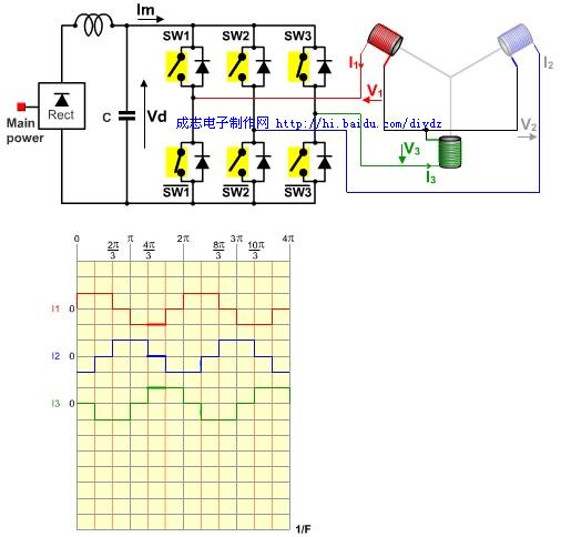
Figure 5
Dongguan Guancheng Precision Plastic Manufacturing Co., Ltd. , https://www.dpowerchargers.com