Method for using universal keyboard of single chip system designed by old computer
This article refers to the address: http://
The calculators are versatile, beautifully crafted, trigger-sensitive, and inexpensive. Using the old calculator to be converted into a general-purpose keyboard of the single-chip system, it can be easily connected with any single-chip application system, whether it is in experimental production or practical application, it is a simple and convenient method.
I used the calculator to make a universal keyboard that was used in several application systems. The effect is better than using ordinary buttons, and it is very convenient to use.
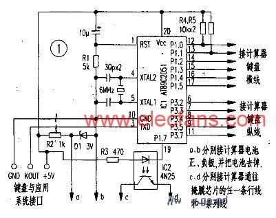
The circuit is shown in Figure 1 and Figure 2. First choose a calculator that looks good and beautiful (this article takes the RS-3890 calculator as an example), open the back cover, find the row and column lines of the keyboard matrix, and mark them. Draw a corresponding map of the matrix keyboard and symbols, as shown in Figure 2.

Cut the line and column lines of the original keyboard to the printed circuit of the mask chip, and then connect the row and column lines to the corresponding L/O port of the AT89C2051 MCU with a fine enameled wire as the detection line of the new keyboard.
In this paper, P1.0 ~ P1.5 for the line, P3.2 ~ P3.7 for the column line, if you need more buttons, the microcontroller can use AT89C51. Use an I/O port of the MCU as the alarm control port (P1.7 in this paper) to control the sound of the original calculator.
Using the serial port of the single-chip microcomputer to output the keyboard code, the work of providing the button control information to the single-chip application system is completed. The keyboard and the application system have only three connections, and the power supply is taken from the application system, which is extremely convenient to use.
The flow chart of the keyboard transmission program and the application system key value receiving program is shown in Fig. 3 and Fig. 4. Write the keyboard code sending source program to 89C2051, the keyboard code receives the source program and writes to the single-chip microcomputer in the application system. The two programs set the same baud rate, use KEYNUM as the keyboard information export, and then according to the KEYREC and KEYNUM values ​​in the application system. As the control program code, the operation of the application system is completed.
| Key code | Key value | key | Key code | Key value |
O | 0lH | 0lH | + | IOH | 14H |
7 | 02H | 0DH | × | llH | 13H |
03H | 1CH | ON/C | 12H | 00H | |
% | 04H | 11H | 2 | 13H | 06H |
05H | 15H | 9 | 14H | 0FHH | |
06H | ICH | 5 | 15H | 0AH | |
07H | 12H | C | 16H | 04H | |
Mr | 08H | 19H | 17H | 16H | |
09H | 02H | 0FF | 18H | OCH | |
MR | 0AH | 18H | 1 | 19H | 05H |
+/- | OBH | 03H | 8 | lAH | 0EH |
0CH | 08H | 4 | 1BH | 09H | |
3 | 0DH | 07H | M- | 1CH | 1AH |
0EH | 17H | M+ | lDH | lBH | |
6 | 0FH | 0BH | lEH | lCH |
The attached table gives the correspondence between the key code and the key value rhyme of the converted after receiving. The key value KEYNUM in the table is defined by the author in an application system, and the reader can also change the key value according to the requirements of the application. The KEYREC value is the actual code issued by the keyboard corresponding to the key shown in Figure 2.

Sdec 0-20Kw Diesel Generator,Sdec Soundproof Power Generator,Sdec Mobile Power Generator,Sdec Canopy Power Generator
Shanghai Kosta Electric Co., Ltd. , https://www.ksdgenerator.com