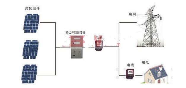
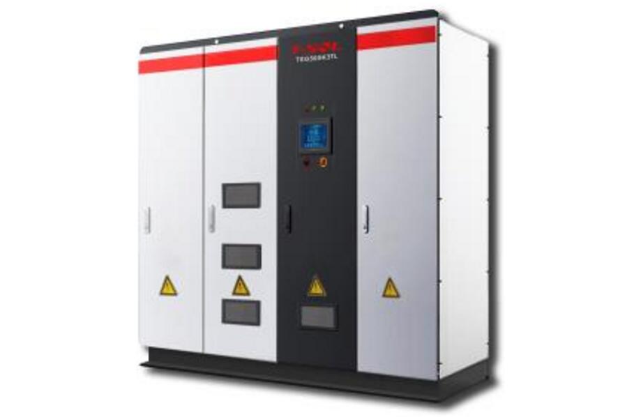
Inverters, also known as power regulators, can be classified into two types, stand-alone power supplies and grid-connected power supplies, depending on the use of the inverter in photovoltaic power generation systems. According to the waveform modulation method, it can be divided into a square wave inverter, a staircase wave inverter, a sine wave inverter, and a combined three-phase inverter. For inverters used in grid-connected systems, they can be classified into transformer-type inverters and transformer-less inverters based on the availability of transformers.
PV inverter structureInverter as a straight AC conversion power adjustment device, divided into two parts of the booster circuit and the inverter bridge circuit, mainly composed of semiconductor devices. The main semiconductor devices are as follows:
1) Current sensor: It requires high accuracy, fast response, low temperature resistance, high temperature resistance, etc. Different current sensors are adopted for different powers. Hall current sensors are generally used for current sampling.
2) current transformer: a wide range of current, generally using BRS series current transformer;
3) Reactors.

The photovoltaic inverter is composed of a boost circuit and an inverter bridge circuit. The boost circuit is mainly used for boosting the DC voltage to the DC voltage required by the inverter. The inverter bridge circuit is mainly used to boost the voltage. The DC voltage is converted to a fixed frequency AC voltage. Therefore, the function of converting the direct current into the alternating current point is accomplished by the boosting circuit and the inverter bridge circuit.
There are ten common faults and treatment methods for photovoltaic inverters1. Abnormal electricity supply
Mains power abnormalities are divided into mains voltage is too low, too high, mains frequency is too low, too high (corresponding to error code F00-F03)
1 Confirm that the safety standard selected by the machine complies with local grid requirements.
2 Check whether the AC output terminals are connected reliably. Use a multimeter to measure the voltage.
3 Disconnect the PV input and restart the machine to see if the machine can return to normal.
4 Failure not ruled out, contact distributor.

2, the insulation resistance is too low
Error code F07
1 Disconnect the PV input and restart the machine to see if the machine can return to normal.
2 Check that the PV+ and PV- resistance to ground is greater than 500KΩ.
3 If it is less than 500KΩ, please contact your local inverter distributor for help or contact the battery supplier.
3, leakage current is too high
Error code F20
1 Disconnect the PV input and restart the machine to see if the machine can return to normal.
2 Failure not ruled out, contact distributor.
4, the ambient temperature, radiator temperature is too high
Error code: F12, F13
1 Disconnect the PV input. After a few minutes, the standby unit cools down and restarts the machine. Observe that the machine can return to normal.
2 Check if the ambient temperature exceeds the normal working temperature range of the machine.
3 Failure not ruled out, contact distributor.
5, monitoring no data
WiFi monitoring:
Connect the inverter to WiFi. Check whether there is an inverter connected to the monitoring page. If there is no inverter information, plug in the built-in WiFi module or check the external WiFi RS485 connection. If no inverter WiFi is found, check it. Whether the built-in WiFi module is in poor contact or external WiFi is not powered.
GPRS monitoring:
Test the signal strength of the Internet connection with the service provider at the installation site of the inverter. Check whether the built-in GPRS module is in poor contact or whether the external GPRS is not powered.
6, low insulation resistance
Use exclusions. Unplug all the strings on the input side of the inverter, and then connect them one by one. Use the function of the inverter to detect the insulation resistance, detect the problem strings, and then check whether the DC connectors have flooding short-circuit brackets after finding the problem strings. Alternatively, the shorting brackets can be melted and the components themselves can be checked to see if the components themselves have black spots burned at the edges and the components leak to the ground through the frame.
7, leakage current failure
The root cause of this kind of problem is the installation quality problem, which is caused by choosing the wrong installation site and low quality equipment. There are many points of failure: low-quality DC connectors, low-quality components, unsatisfactory installation height of components, low quality of grid-connected equipment, or leakage of incoming water. Once similar problems occur, you can find out the Good insulation work to solve the problem, if it is the material of this province can only replace the material.
8, the inverter boot no response
Make sure that the DC input circuit is not reversed. Generally, the DC connector has a foolproof effect, but the crimping terminal has no fool-proof effect. It is important to carefully read the inverter instructions to ensure that the positive and negative terminals are crimped. Inverter built-in reverse short-circuit protection, normal start after restoring normal wiring.
9, power grid failure
Overvoltage in power grid: The work of pre-investigating power grid heavy load (large working hours for power consumption)/light load (reducing power consumption time) is reflected here, and the health status of voltage points at the outlets is surveyed in advance, and the inverter manufacturers Communicating the situation of the power grid and combining technology can ensure that the project design is within reasonable limits. Do not “take it for grantedâ€, especially for rural power grids, inverters with grid voltage, grid-connected waveforms, and grid-connection distances are all strictly required. The majority of power grid overvoltage problems occur because the original power grid light load voltage exceeds or approaches the safety protection value. If the grid connection line is too long or the pressure connection is not good, the line impedance/inductance is too large, and the power station cannot operate normally. The solution is to find the power supply bureau to coordinate the voltage or to properly select the grid connection and strictly control the quality of the power station construction.
Grid undervoltage: This problem is consistent with the grid overvoltage treatment method. However, if an independent one-phase voltage is too low, in addition to the original grid load distribution is incomplete, the phase grid power loss or open circuit can also lead to the problem. Virtual voltage.
Grid over/under frequency: If the normal grid has such problems, it proves that the grid health is very worrying.
The grid has no voltage: check the grid connection.
Grid phase missing: Check for missing phase circuits, ie no voltage lines.
10, DC overvoltage protection
With the pursuit of high-efficiency process improvement of the components, the power level is continuously updated, and the open circuit voltage and the operating voltage of the components are also rising. The temperature coefficient must be considered in the design stage to avoid overvoltage in the low-temperature conditions and hard damage to the equipment.

Trend 1: High-speed development of inverter hardware
The use of various new devices such as SiC, CAN, and high-performance DSPs, and the application of new topologies, has led to continuous improvements in the efficiency of inverters. At present, the maximum efficiency of inverters has reached 99%, and the next goal is 99.5%; China's efficiency has been improved. Reach A level, the next goal is A+, A++.
Trend 2: Centralized inverter power increases, efficiency increases, and voltage level increases
Inverters with higher power levels such as 2.5MW will be widely used. Compared with 1MW square arrays, 2.5MW solutions can reduce costs by about 0.1 yuan/W, that is, 100MW power plants can reduce initial investment by 10 million. In addition, after the cable is matched, the loss of the DC part is ensured.
It is worth mentioning that the 1500V system will be the development trend of large-scale power plants. Compared with the 1000V system, the investment of 0.2 yuan/W can be saved in addition to the components, equivalent to a savings of 20 million yuan for a 100MW power plant. At the same time, system losses can be reduced by approximately 0.27%.
Trend 3: The single-unit power of the string inverter keeps increasing and the power density increases
The power of the string inverters has been continuously increased. At present, the maximum power has been increased to 80 kW, the power density is also increasing, and the weight is continuously reduced to meet the complex application environment where installation and maintenance are difficult. Solar Power's 40kW string inverter has achieved 39kg, which is the lightest 40kW product in the industry. In respect of heat dissipation, Sungrow Power has always adhered to smart fan cooling methods to further reduce the temperature rise of internal components and increase the overload capacity of the inverter in high temperature environments. The fan protection rating used is IP65 and the lifetime can reach 70,000 hours. At the same time, the fan can provide a 20-year warranty.
Trend 4: Increasingly richer component-level products (MLPE)
Component-level products are becoming more and more abundant, such as micro-inverters represented by Enphase and power optimizers represented by SolarEdge. According to industry research agency GTM, shipments of component-level power electronics (MLPE) equipment will increase from 1.1 GW in 2013 to over 5 GW in 2017.
Trend 5: The adaptability of power grids continues to increase, and various types of protection are more complete, ensuring safety and reliability
Protection functions such as leakage current protection, SVG function, LVRT, DC component protection, insulation resistance detection and protection, PID protection, lightning protection, and PV positive and negative reverse polarity protection, and the ability of the inverter to adapt to the power grid is further enhanced and continuously improved. The protection function makes the system more secure and reliable.
Trend 6: The environmental adaptability of the inverter continues to increase
With the increasing application of photovoltaic power stations in harsh environments such as coastal areas, deserts, and highlands, the environmental resistance of anti-corrosion and anti-sanding of inverters has been continuously improved to ensure high reliability in harsh environments.
When talking about the development trend of photovoltaic systems, Zhao Wei stated that through the application of various new technologies and new products, the progress of photovoltaic technology will continue to be promoted, system efficiency PR will be improved, and the cost of electricity (LCOE) within the system life cycle will be reduced. Cheaper Internet access is the goal of everyone's common struggle.
The design of the power station will be more refined; the degree of system integration will be further improved, and the integrated solution of integrated inverters and medium voltage transformers will be able to simplify the system to the extreme, while reducing costs, facilitating use, improving efficiency, and improving reliability.
The development of photovoltaic inverter industry is in the ascendant, and various new technologies and products are changing with each passing day, which can be described as local conditions and contend; in large ground power stations, the initial investment of centralized solutions is lower, and the subsequent operation and maintenance costs are only 1/3. The results of a number of power plant operations show that the string and centralized power generation are equal, which is the user's first choice; 2/2.5MW solutions will become the mainstream next year; string inverters are also increasingly used in distributed applications. Many, high power, high efficiency, high power density is the future direction of development; PV + Internet for the majority of customers recognized, digital smart power station will become the mainstream; photovoltaic + energy storage applications have broad prospects.
ceramic cap
ceramic cap
YANGZHOU POSITIONING TECH CO., LTD. , https://www.cnpositioning.com