The airborne station is responsible for communication between air and ground, and in order to ensure the performance of the radio, it needs to be checked. The detector based on single-chip microcomputer has the problems of slow measurement speed and poor scalability; and the detector based on PXI instrument or VXI instrument has the disadvantages of large power consumption, large volume and high price. In order to solve the above problems, the use of ARM-based processor to implement the radio detection controller has become an important development direction. ARM is a high-performance, low-power RISC structure processor, which is widely used in industrial control due to its excellent performance. In wireless communication, imaging and security, network applications, etc., the ARM-based radio detection controller has the advantages of strong portability, good scalability, and strong anti-interference ability.
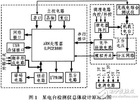
1 hardware designGood hardware design is the key to solving the problem of radio detectors based on single-chip, PXI, VXI and other systems. In order to realize the modular design of the hardware structure, the hardware is mainly divided into two parts: the main controller circuit and the conditioning circuit. In order to design a high-performance, low-power, scalable and low-cost detector, the choice of the main controller is crucial. To meet the scalability of the detector, the main controller must have network functions, USB storage, Serial communication, SPI communication, I2C communication, analog-to-digital conversion and other functional modules, in order to meet the requirements of human-computer interaction design, must also have the necessary frequency preset circuit, display circuit and so on. A controller with such a versatile controller and a controller that satisfies high performance and low power consumption can only be completed by an ARM processor. According to the electrical characteristics of a station, the communication between the master and the station must also perform the necessary level shifting. In addition, the response signal output from the station cannot be directly sent to the main controller. The necessary voltage divider network and impedance matching must also be performed. Such circuit design, which requires conditioning circuitry. The main controller circuit and the conditioning circuit cooperate to complete the detection of the radio. The overall structure of the hardware designed according to the radio test requirements is shown in Figure 1.

1.1 main controller
The main control is the core of the radio detection controller. It is responsible for important tasks such as information collection, storage, network function and radio communication. The quality of the main control also directly determines the system performance. After comparison, Philips LPC2388 is selected as the radio station. The main controller, the device is based on the ARM7TDMI-S core processor, with a network of peripheral controllers, USB controller, I2C, serial interface and other rich peripherals, to meet the needs of the detector.
1.2 storage circuit
In order to meet the requirements of scalability and storage of test results, the detection controller must save the results of each measurement on a certain type of station. This requires communication between the main controller and the radio integrated tester. The integrated tester has a serial communication mode for external communication. When measuring, the communication control interface can be connected to the radio integrated serial line, so that the test result can be read into the control system. If the information is to be stored, the memory must be satisfied. Rewritable, in order to save the controller's valuable general-purpose I / O port, choose CAT24WC64 with 12C communication storage function as E2PROM, the device is responsible for saving the radio performance test results, save up to 50 radio test results, more than 50 times, the system automatically Erasing the original stored test results and then storing them. When you need to view the system radio test results, you can use 3 methods: 1) Insert the USB storage device into the USB storage interface circuit, the system will automatically recognize the device, and then select the Store Test Results button to save the saved test results to the USB storage. Equipment: 2) Connect to the computer through the network interface, and then use the remote control to read the test results: 3) Use the serial communication method to read the information into the computer.
1.3 USB storage interface circuit
The USB interface circuit is a window for communication with the USB storage device. The LPC2388 has a controller compatible with the USB2.0 protocol. This controller provides convenience for the USB interface design. To meet system reliability, a 33 Ω resistor is connected in series on the D+ and D- lines, and a 1.5 kΩ pull-up resistor is added to the D+ to indicate that the USB storage device is connected to the Ul_UPLED pin. Add an indicator light on the USB storage device when it is connected.
1.4 network interface circuit
To meet the needs of remote control, the test controller should have a network control interface. The LPC2388 has a 10/100 Mb/s Ethernet communication rate to ensure reliable transmission, using a high-speed AHB bus communication between the 16-byte-byte Ethernet controller-specific SDRAM, the Ethernet controller and the ARM7 core. A dedicated DMA is used for data transfer. The Ethernet controller used inside the processor uses the RMII interface to communicate with the peripheral circuit PHY chip DM916lA to implement the Ethernet communication function.
1.5 frequency forming circuit
In order to fully detect the performance of the radio, the radio detector should detect the performance of the radio at multiple frequency points. This requires the detector to output a variable frequency control code. The formation of the frequency control code requires a frequency forming circuit. The frequency forming circuit is pulsed, counted, and finally buffered and sent to the main controller. The pulse forming circuit is realized by a self-reset switch, and the shaping circuit is realized by using the MAX708 counting and buffering circuit by using 54HCl90 and 54LVC245 respectively. To save the valuable I/O port resources of the processor, the analog bus is used to realize, by latching, A decoding circuit controls the formation of the frequency code.
1.6 display, keyboard circuit
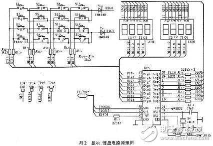
The display circuit is a human-computer interaction window that directly displays the current state of the detector and the station detection result. When the detected station cannot meet the performance requirements, the error result is directly displayed; the keyboard circuit completes the input of some functions of the detector. In order to ensure the reliability of the tester display results, the detector display circuit adopts LED digital tube display with strong anti-interference ability. The driver of LED digital tube selects ZLG7290, ZLG7290 uses three-line serial code to interact with ARM processor for dynamic display. Features reduce system power consumption. In addition to the ZLG7290 used to drive the display digital tube, part of the input detected by the radio is also realized through its keyboard interface. The circuit diagram is shown in Figure 2.

1.7 Other circuits
A system can work reliably, must have a series of circuit guarantees such as crystal oscillation, watchdog, power supply, etc., provide the clock and monitoring circuit necessary for the system to work, the crystal oscillator circuit provides the necessary clock signal, and the watchdog circuit appears in the program operation. When an abnormality is provided, the microcontroller provides a reset signal, which increases the robustness of the system: the power supply circuit is the entire system power supply, and the DC/DC switching power supply with high conversion efficiency is adopted, and the system design power is supplied according to the function, that is, the control circuit power supply and The conditioning circuit is independently powered: it increases the system's immunity to interference.
1.8 conditioning circuit
The detection controller's working state and working timing are completed by the main controller. However, this is only one aspect of detecting the normal operation of the controller. Another important aspect is the conditioning circuit, which is mainly composed of a relay array, a voltage divider network, and an analog switch. , level conversion and other components. The signal output by the controller can't be directly added to the radio. There are two main reasons: 1) The serial port data output by the test controller is a single-ended output, and the signal required by the radio is a differential signal; 2) The controller output The signal level and format are completely correct. To ensure the anti-interference of the system, a buffer is generally added to the output of the controller and the input of the radio to increase the isolation between the system modules. All control information of the detection controller panel is sent to the radio through the serial port after being processed by the processor, and the radio station needs a differential signal, and the DSl6F95 is used to realize the conversion of the signal level mode. In addition to testing the performance of the transceiver, the test controller can also test the performance of the control box. In addition, the control can be used to control the transceiver, so that the control box on the analog control box can control the transceiver. The control box can not be sent to the control box itself. Radio, which requires a relay array to complete the transition between the detector and the control box. In addition, in order to monitor the working voltage of the radio, the detector should display the working voltage in a time-sharing manner, and the working station 27V and the internal transceiver control voltage should also be displayed. These voltages need to be divided and sent to the numerical control analog switch after the voltage divider network. Monitor each voltage in turn.
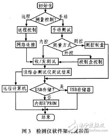
2 software architecture designThe radio detection controller is a typical embedded control system, and its performance design is directly related to whether the system can work reliably. The embedded software design is quite different from the ordinary PC software. Due to the complex control relationship of the detector, plus the network interface, USB storage driver, interrupt time control, timer design, serial communication and other factors, the software architecture requirements. Higher, software and hardware detection coordination must be considered, and the software must also meet the design of testability, portability, robustness, etc., and consider a variety of factors. The software flow of the station detection controller is shown in Figure 3. After the system is powered on, it is initialized and then selected for measurement control. If it is remote control, the network connection is started, the computer is used to control the detection controller to work, and the transceiver performance test is entered. The test result is stored in the remote computer through the network; Manual test, it is judged whether the measurement method is measurement and control, external control or measurement and control. If it is internal control, the transceiver controls the transceiver, and the main performance of the transceiver is measured by the radio comprehensive tester. By reading the radio comprehensive tester The test result can save the result. If the USB storage device exists, the result exists in the result of saving the result. Otherwise, it is stored in the internal rewritable E2PROM; if it is measurement and control, the detection controller measures the status of the control box. And save the result; if it is external control, the transceiver performance is measured under the control of the control box, and the test controller also saves the test result by reading the radio comprehensive tester result.

Based on ARM, the radio detection controller has flexible hardware design and good software architecture design. It realizes seamless integration of software and hardware platform. It has high performance, low power consumption, good portability, and good scalability. Detection and control. Through the network interface, remote control can be realized, and the measurement result can be read in real time: by adding a USB storage interface, the measurement data can be directly saved in the case of manual testing, which greatly improves the processing speed of the test result, and has a broad Economic and military benefits.
Fiber Optic Patch Panel,Fiber Patch Panel,Fiber Distribution Panel,Optical Patch Panel
Cixi Dani Plastic Products Co.,Ltd , https://www.danifiberoptic.com