The 30W soldering iron feels heated for a long time during the soldering of large components, which makes it easy to damage the soldered components.
If you want to open a hole in the plastic and feel that the heat is too large, it is easy to cause the opening to be too large. The plastic melts too much and sticks to the iron core. It is difficult to remove carbonization.
During the debugging process, the intermittent use of the soldering iron has been in a dry burning state, and the painful iron core is easily oxidized. If the iron core is protected from power failure, it is necessary to wait for the heating time again.
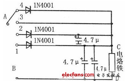
So I thought about it for a long time and thought of a way to avoid the above situation. First, the thermostat circuit of the soldering iron is drawn as shown in the figure. In fact, the components are very simple, a multi-throw switch, three 400V/4.7uF capacitors and three 1N4001 diodes and wires. There is a three-phase plug and a debut socket. Here, a friend can ask where there is a three-phase electric soldering iron. In fact, this is to prepare for another important function. That is grounding, because the induction iron has enough inductive power to allow the integrated circuit to break down, so grounding to release these charges.
A plastic insulation box is also required, which can be replaced by a plastic box of a rectifier of a broken fluorescent lamp. Of course, other plastic boxes are also available. Solder the original to the switch according to my circuit diagram. Then connect the A and B terminals to the live and neutral lines of the plug, and connect the C and D terminals to the live and neutral lines of the socket. Screw a copper wire onto the root vent of the soldering iron steel jacket and connect it to the ground terminal of the three-phase plug. This is all done.
working principle:
When the selection switch is connected to 1, a diode is connected in series in the circuit, which is equivalent to a half-wave rectification circuit. At this time, the electric iron only uses the positive half wave of the alternating current to work. It is equivalent to reducing the power of the soldering iron, only the usual 70% power, plus the temperature loss, the heat is only 60% of the original, just used for hot baking and waiting for insulation during debugging, will not cause oxidation of the soldering iron .
When the switch is selected to 2, it is normal power, which is suitable for soldering small components. When the switch is selected to 3, although a diode is connected in series to form a half-wave rectifier circuit, we have a 400V/4.7uF capacitor connected in parallel with the load of the soldering iron. The rectified DC power is then boosted by a capacitor to a 280V power supply. However, the power of the soldering iron is also increased by 30% after the voltage is raised, so that it is much more convenient to solder large components with high temperature. When the switch is connected to 4, it is also half-wave rectified but there are two capacitors boosting, there will be 300V voltage, the temperature will be higher, so a multi-stage temperature adjustment soldering iron will be produced.
After that, a 60W high-power electric soldering iron was also modified. It turns out that there is always no use of power because it is too powerful. Remove a dimming circuit from a used dimming light, just as the power is 60W. The two ends of the dimming circuit are connected to the circuit of the soldering iron, so that a stepless power regulating electric soldering iron is born. The power can be adjusted from a few watts to 60W, if equipped with a meter that can measure temperature. Then it becomes a soldering iron that can set the temperature.

Guangzhou Yunge Tianhong Electronic Technology Co., Ltd , http://www.e-cigaretteyfactory.com