Key words: "room in the room" structure vibration isolation internal resonance metal spring isolator fiber material
1 Introduction:
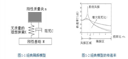
Vibration isolators are widely used in vibration isolation engineering to protect instruments and equipment from vibration or to attenuate the external propagation of machine vibration. The classical vibration isolation model is shown in Figure 1-1. The model assumes that the vibration isolator consists of an ideal spring and damping without mass, and the vibration isolation object and foundation are ideal rigid bodies. The theoretical transfer rate of the classical model is shown in Figure 1-2. When the excitation frequency is greater than the resonance frequency of the system, the instantaneous transmission rate T<1, the vibration isolator acts as a vibration isolation, and the theoretical transmission rate increases with frequency. Attenuation is 12dB per octave. At that time, the transmission rate T>1, the vibration isolator is in the resonance region, and the vibration isolator increases the amplitude of the vibration isolation body. [1,2]
In the actual vibration isolation system, the basic non-rigidity, the non-rigidity of the protected object, and the mass distribution of the vibration isolator will reduce the high-frequency vibration isolation performance, resulting in a high-frequency transmission rate greater than that of the ideal isolators. And periodic peaks appear. [3,4,5,6]
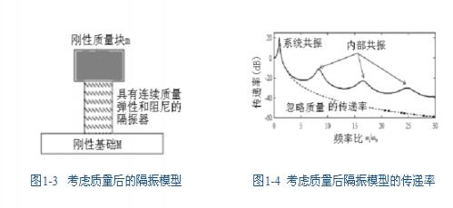
The vibration isolation model considering the mass is shown in Figure 1-3. At this time, the vibration isolator has continuous distribution quality, elasticity and damping. The transmission rate curve is shown in Figure 1-4. When the length of the isolator is comparable to an integral multiple of 1/2 wavelength of the vibration propagating in the isolator, that is, when the excitation frequency is greater than a certain value, the vibration propagates in the form of elastic wave, and the mass of the isolator itself The vibration isolation performance of the isolator is reduced. This phenomenon is called internal resonance or wave effects, hereinafter collectively referred to as "internal resonance." At this point, the isolator no longer meets the no-mass hypothesis and should be considered a distributed quality system. As can be seen from Figures 1-4, the internal resonance significantly increases the high frequency transfer rate and causes a periodic peak in the transfer rate. [3,4,5,6]
Mark Harrison et al. [7] theoretically derived the causes of internal resonance and derived the theoretical transfer rate formula. The theoretical calculations are in good agreement with the experimental results. A study by Mark Harrison et al. found that the standing wave effect can reduce the high-frequency transmission rate of the isolator by 20 dB.
Y. Du et al. [8] studied the effects of internal resonance generated by the mass distribution of the isolator by establishing a mathematical model. The article compares the ideal vibration isolator that ignores the mass and the transmission rate of the vibration isolator after considering the mass. It is found that the transmission rate increases by 20-30dB after considering the mass of the vibration isolator. At the same time, they also compare the noise of the basic vibration radiation, and found that the noise of the fundamental vibration radiation can be increased by 22 dB after considering the mass of the vibration isolator. The internal resonance of the spiral metal spring isolator is more significant than that of the rubber isolator. Numerical simulations found that the following three factors significantly affect the frequency and amplitude of internal resonance: (1) the mass ratio of the vibration isolators to the isolators; (2) the Young's modulus of the isolators; and (3) the damping. (1) Increasing the mass ratio can reduce the influence of internal resonance and reduce the transmission rate of the isolator. (2) The Young's modulus of the isolator is mainly related to the frequency of internal resonance, reducing the Young's modulus of the isolator, and the frequency of internal resonance is also reduced, and more will appear in a given frequency range. Internal resonance. The traditional model ignores the quality of the isolator, and the lower the resonance frequency of the system, the better the high-frequency vibration isolation performance. The offset of the internal resonant frequency of the actual isolators may make this conclusion no longer valid. (3) Increasing the damping can significantly reduce the transmission rate of the internal resonance peak.
Xiong Yeping's research [5] found that the basic non-rigidity causes the frequency of internal resonance of the isolator to shift to the low frequency direction. The fundamental resonance and the standing wave effect of the isolator make the vibration transmission rate peak. Intensive and towering. [page]
J. Lee et al. [9] found that when the vibration exceeds a certain frequency, the internal resonance of the isolator significantly affects the elastic modulus of the metal spring isolator, so that the spring dynamic modulus increases rapidly with increasing frequency. The increase causes the internal resonance of the metal spring to be more serious, reducing the high-frequency vibration isolation capability. For rubber isolators [10], the dynamic elastic modulus also increases with increasing frequency: for low damping rubber materials, including natural rubber, carbon black reinforced rubber, SBR (Styrene Butadiene Rubber) rubber, usually considered In the frequency range, the dynamic elastic modulus increases little with frequency; and the high damping rubber material, including Thiokol RD rubber, carbon black reinforced butyl rubber, polyvinyl acetate adhesive, dynamic elastic mold The amount increases rapidly as the frequency increases.
The above research is mainly applied to industrial vibration isolation, especially for vibration isolation of automobiles and other machinery. In buildings, buildings with particularly high requirements for architectural acoustics, such as recording studios, studios, and acoustic laboratories, as well as buildings with strong vibrations such as traffic trunks, use a large number of "room-in-room" structures to isolate vibration. The vibration isolation structure of the "room in the room" and the general vibration isolation system are very different in terms of scale, material and structure. This paper builds a test bench based on the National Grand Theater Recording Studio and the Architectural Acoustics Laboratory of Hebei Engineering College. The actual vibration isolation performance of different "room-in-room" vibration isolation structures compares the advantages and disadvantages of different vibration isolation methods.
2. Experimental method
Metal spring isolator vibration isolation experiment
The experiment was carried out in the standard sound insulation laboratory of the School of Architecture of Tsinghua University. The sectional view of the vibration isolation experiment and the layout of the spring isolator are shown in Figures 2-1 and 2-2, respectively. This group of experiments is based on the National Grand Theater Recording Studio. The vibration isolation system consists of four metal spring isolators designed to resonate with the system. The “Room in the Room†floor is a 300mm cast-in-place reinforced concrete structure with a weight of 10T, which is completely supported by the vibration isolator and has no rigid connection with the foundation. In order to make the isolator load bearing the same as that of the National Grand Theater Recording Studio, press 30T bricks on the 300mm floor. The "room in the room" is based on a 100mm reinforced concrete structure. In order to support the foundation to support the weight of 40T, it is supported by scaffolding on the receiving chamber. As can be seen from Figure 2-1, the basis of the "room in the room" structure is the receiving chamber, which is also supported on the spring, not a rigid foundation. The non-rigidity of the foundation affects the vibration isolation performance of the "room in the room" structure, which is described in more detail below.
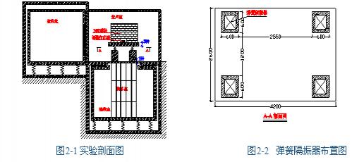 The experiment studied the vibration isolation performance by measuring the impact sound pressure level of the "room in the room" structure. The experiment uses a standard striker to select three equally spaced points on one diagonal of the "room in the room" floor, and measure the impact sound pressure level in the receiving room, and then according to the reverberation time T of the receiving room. Sound pressure level is corrected [11, 12]:
 (2-1)
Where: ——corrected impact sound pressure, dB; ——impedance sound pressure level measurement value, dB; ——the sound absorption under standard conditions, specified as 10m2; A——the sound absorption of the receiving room, M2; K - the constant associated with the speed of sound, usually 0.161; V - the volume of the receiving chamber, m3; T - the reverberation time of the receiving chamber, s.
The article uses the corrected impact sound pressure level to evaluate and study the vibration isolation performance of the "room in the room" structure. Obviously, the lower the sound pressure level of the impact sound, the less the vibration transmitted to the receiving chamber, and the better the vibration isolation performance of the vibration isolation structure of the "room in the room". The experimental measurement method is referred to the "Code for Measurement of Building Sound Insulation" (GBJ 75-84). The measuring instrument is Norsonic's RTA840 system and standard striker.
Fiber material vibration isolation experiment
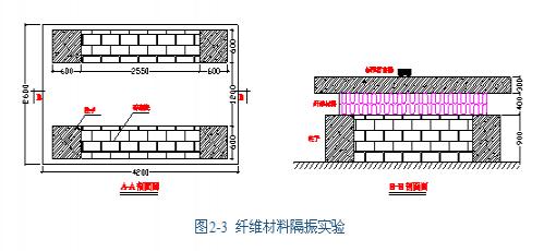
The spring vibration isolation structure is a multi-point support method, and the vibration isolation of the fiber material is a surface support, and the two are greatly different in the force situation and the design method. This group of experiments is based on the Architectural Acoustics Laboratory of Hebei Institute of Engineering. The Architectural Acoustics Laboratory of Hebei Institute of Engineering consists of a semi-anechoic chamber and a reverberation chamber. Both laboratories adopt a “room-in-room†structure, which uses a centrifugal glass wool with a weight of 80kg/m3 to support the “room in the roomâ€. The load per unit area of ​​the damping material is 2500kg/m2 and 3300kg/m2, respectively. The experimental scheme was reconstructed on the basis of the spring vibration isolation experiment. Two rows of load-bearing walls with a surface area of ​​3 m2 were built with cement bricks between the four supporting columns, and the vibration-damping materials were tested on the load-bearing wall cushion for vibration isolation experiments. Figure 2-3 shows. According to the unit load of the vibration-isolating material, the 30T pressure brick was eliminated, so that the vibration-damping material had a load per unit area of ​​3300kg/m2, which was consistent with the experimental prototype.
The measurement method is the same as the spring isolation experiment.
3. Experimental results and analysis
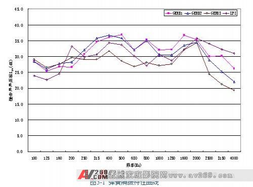 GERB1: elastic coefficient K=7.2KN/mm, damping ratio=0.10, special rubber pad for 2mm upper and lower pads
 GERB2: elastic coefficient K=9.4KN/mm, damping ratio=0.10, special rubber pad for 2mm upper and lower pads
GERB3: elastic coefficient K=9.4KN/mm, damping ratio=0.10, special rubber pad for 2mm pad, special rubber pad for 10mm under pad
LPI: elastic coefficient K=3.4KN/mm, damping ratio=0.00, special rubber pad for 3mm pad, special rubber pad for 14mm under pad
Figure 3-1 shows the LPN curve of the impact sound pressure level after the rubber cushion of the spring isolator with different elastic modulus and damping. GERB1 to GERB3 are provided by Separation and Solid (Qingdao) Vibration Isolation Technology Co., Ltd., LPI by Beijing Provided by the Labor Protection Institute. It can be seen from the curve that the impact sound pressure level Lpn does not decrease with increasing frequency, but remains at a high level and periodically fluctuates. It shows that the high-frequency vibration isolation performance of the spring isolator does not increase with the increase of the frequency. The vibration isolator no longer conforms to the classical vibration isolation model at high frequency. At this time, the mass of the vibration isolator and the non-rigidity of the foundation cannot be ignored. The internal resonance caused by the distribution quality of the isolator and the non-rigidity of the vibration isolation base significantly reduce the high-frequency vibration isolation capability and make the high-frequency impact sound pressure The stage has periodic fluctuations.
Comparing the GERB1, GERB2 and GERB3 curves, it can be seen that the spring pad is thicker under the vibration isolator, that is, the elastic modulus of the rubber pad is reduced, and the high-frequency vibration isolation performance of the spring isolator can be significantly improved.
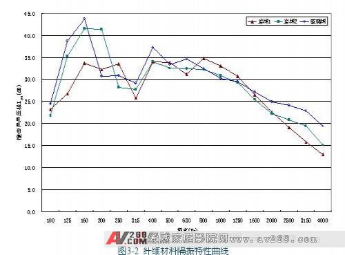 Rock wool 1: bulk density = 140kg/m3, static sinking degree;
 Rock wool 2: bulk density = 140kg/m3, static sinking degree;
Glass wool: bulk density = 96kg/m3, static sinking degree;
Figure 3-2 shows the sound sound pressure level Lpn curve of different fiber materials during vibration isolation. The fiber material is provided by Beixin Group. It can also be seen from the curve of Fig. 3-2 that the percussion sound pressure level Lpn does not always decrease with increasing frequency, and periodic fluctuations also occur. Experiments show that the fiber material does not conform to the classical vibration isolation model at high frequencies, and the internal resonance of the fiber material and the basic non-rigidity also significantly reduce the high-frequency vibration isolation capability.
Comparing Fig. 3-1 and Fig. 3-2, it can be found that at high frequency, the impact sound pressure level Lpn of the metal spring isolator has been maintained at a high level, and the impact sound pressure level Lpn of the fiber isolator is gradually reduce. It is indicated that the internal resonance of the high frequency of the metal spring isolator is more serious than that of the fiber isolator. The research in [6] shows that due to the internal resonance, the dynamic elastic coefficient of the metal spring increases rapidly with the increase of the frequency, and the transmission rate of the spring isolator increases with the increase of the elastic coefficient. The transfer rate of the metal spring isolator is kept at a high level. This is consistent with the experimental results. At low frequencies, comparing Figure 3-1 with Figure 3-2, it can be seen that the vibration isolation performance of the metal spring isolator is better than that of the fiber material. This is because the internal resonance spring isolator has a smaller elastic modulus than the glass fiber and the system resonance frequency is low. .
4. Summary
The article establishes a test bench based on the National Grand Theater Recording Studio and the Architectural Acoustics Laboratory of Hebei Institute of Engineering. The vibration isolation performance of the “room in the room†structure is obtained by measuring the impact sound pressure level Lpn of different “rooms in the room†structure. The following conclusions:
(1) Experiments have shown that the high-frequency vibration isolation performance of the "room-in-room" structure is significantly reduced due to the internal resonance of the isolator and the non-rigidity of the foundation.
(2) The internal resonance of the metal spring isolator is more serious than the fiber material, which results in the high-frequency vibration isolation performance of the metal spring is not as good as that of the fiber material. After the rubber pad is padded, the high-frequency vibration isolation performance of the spring isolator can be significantly improved.
Acknowledgement:
I would like to thank the Owners' Committee of the National Centre for the Performing Arts, the Separation (Qingdao) Vibration Isolation Technology Co., Ltd., the Beijing Labor Protection Science Research Institute and the Beixin Group for their support.
references:
[1] Cyril M. Harris, Handbook of Noise control, second edition, McGraw-hill book company, New York, 1979.
[2] Ma Dazhao, Shen Wei, Acoustics Handbook (Revised Edition), Beijing: Science Press, 2004.
[3] Ungar, EE; Dietrich, CW, "High-frequency vibration isolation" Journal of Sound and Vibration 1966 pp. 224-241.
[4] Dai Depei, Damping Vibration Reduction and Noise Reduction Technology, Xi'an: Xi'an Jiaotong University Press, 1986.
[5] Xiong Yeping, Song Kongjie, Research on standing wave effect in flexible vibration isolation system, Journal of Shandong University of Technology, 25 (1995) 108-113.
[6] Soliman, JI; Hallam, MG, "Vibration isolation between non-rigid machines and non-rigid foundations" Journal of Sound and Vibration 1968 pp. 329-351.
[7] Mark Harrison, Alan O. Sykes, M. Martin. Wave Effects in Isolation Mounts. J Acoust Soc Amer, 24 (1952) 62-70.
[8] Y. Du, RA Burdisso, E. Nikolaidis, D. Tiwari, Effects of isolators internal resonances on force transmissibility and radiated noise, Journal of Sound and Vibration 268 (2003) 751–778.
[9] J. Lee, DJ Thompson, Dynamic stiffness formulation, free vibration and wave motion of helical springs, Journal of Sound and Vibration 239 (2001) 297–320.
[10] Snowdon, JC, "Rubberlike materials, their internal damping and role in vibration isolation" Journal of Sound and Vibration 1965 pp. 175-193.
[11] GBJ 75-84, Building Sound Insulation Measurement Specification.
[12] Qin Youguo, Wang Binglin, Architectural Acoustic Environment (Second Edition), Beijing: Tsinghua University Press, 1999.
The bending and forming of the metal plate is carried out on the bending machine. Place the workpiece to be formed on the bending machine, lift the brake shoe with the lifting lever, slide the workpiece to the proper position, and then lower the brake shoe to the workpiece to be formed, and realize the bending of the metal by applying force to the bending lever of the bending machine.
Sheet Metal,Forming Mount Unit,Laser Cutting Cover,Sheet Metal Forming Process
Dongguan Formal Precision Metal Parts Co,. Ltd , https://www.formalmetal.com