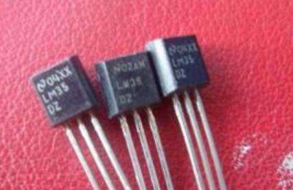
The LM35 is a temperature sensor manufactured by NaTIonal Semiconductor and its output voltage is Celsius. The LM35 is a widely used temperature sensor. Since it uses internal compensation, the output can start at 0 °C. The LM35 is available in a variety of different package styles. At room temperature, the LM35 does not require additional calibration to achieve ±1/4°C accuracy.
Classification introduction
The power supply mode is single power supply and positive and negative dual power supply. Its pin is shown in Figure 1. The positive and negative dual power supply modes can provide negative temperature measurement; the static current-temperature relationship of the two connections, The self-heating effect is low (0.08 °C) in the static temperature, the single-supply mode has a static current of about 50 μA at 25 °C, and the working voltage is wide, which can work normally in the range of 4-20V supply voltage.
The operating voltage is 4 to 30 V. Within the above voltage range, the current absorbed by the chip from the power source is almost constant (about 50 μA), so the chip itself has almost no heat dissipation problem. This small current also makes the chip particularly suitable for some applications. For example, in a battery-powered application, the output can be taken out of the third pin without calibration at all.
Currently, two models of the LM35 are available for use. The LM35DZ output is 0 ° C ~ 100 ° C, and the LM35CZ output can cover -40 ° C ~ 110 ° C, and the accuracy is higher, the accuracy of both chips is higher than the LM35, but the price is slightly higher.

Specifications
1, working voltage: DC 4 ~ 30V;
2, working current: less than 133μA
3, the output voltage: +6V ~ -1.0V
4. Output impedance: 0.1Ω at 1mA load;
5, accuracy: 0.5 ° C accuracy (at +25 ° C);
6, leakage current: less than 60μA;
7. Scale factor: linear +10.0mV/°C;
8, non-linear value: ± 1/4 ° C;
9, calibration method: directly with Celsius temperature calibration;
10, rated operating temperature range: -55 ~ +150 °C.
11, pin description: 1 power supply negative GND; 2 power supply is VCC; 3 signal output S;
Sensor parameter
Supply voltage 35V to -0.2V
Output voltage 6V to -1.0V
Output current 10mA
Specified operating temperature range
LM35A -55°C to +150°C
LM35C, LM35CA -40°C to +110°C
LM35D 0°C to +100°C
High-precision constant temperature control system based on LM35 temperature sensorTemperature control is widely used in people's production and life, such as large-scale farms, artificial climate, soilless cultivation and many other occasions. In these cases, people use a large number of thermometers to collect the temperature. We know that most of the metrology tools need to be regularly calibrated (normally the next year or half a year). However, once installed, the temperature measuring instruments in these applications are often difficult to send to the metrology department for calibration. Therefore, it is very important to quickly detect and correct the temperature control process curve online. To this end, the author developed a calibration control system for metering and transmission using PID control technology, and a fully automatic temperature analysis system for PID parameter measurement and adjustment.
System hardware design
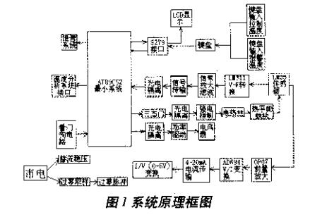
The system block diagram is shown in Figure 1. Compared with conventional A/D conversion, this system has the following advantages:
1. M35 cooperates with a special V/F converter, which has good linearity of conversion, high precision, and is convenient for further improving measurement accuracy by using single-chip microcomputer;
2. Since the V/F conversion itself is an integral mode, the anti-interference ability is strong;
3, in the V / F conversion output is a pulse, easy to achieve optical isolation;
4. The number transmission only occupies one data port, the interface is convenient and the cost is low;
5. Remote transmission for remote temperature control.
Secondly, when designing the system, it is easy to arrange functional circuits with strong electrical isolation, temperature rise control, display, alarm, and number reporting. Therefore, the system is reliable and practical, and the only shortcoming is that the acquisition speed is slow, but for the temperature control of the general speed, the proper design can still obtain high-precision control quality.
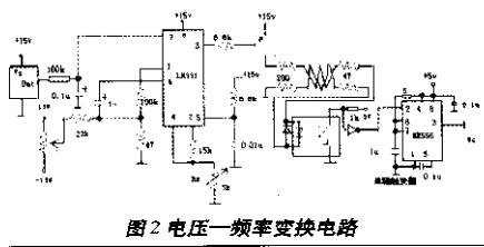
(1) Temperature measurement and V/F conversion circuit See Fig. 2: The sensitivity of the sensor LM35 is 10mV/°C, which is suitable for use with the VF dedicated chip LM331. The signal is directly sampled and filtered from the output of the LM35 and sent to the LM331 for VF conversion, and 200mV~1500mV corresponds to 200Hz~1500Hz. In order to enhance the anti-interference ability of the signal, photoelectric isolation is performed at the time of signal conversion. In order to improve the measurement accuracy and adapt to the requirements of the measurement cycle, the frequency signal is divided by the 555 chip.
(2) Voice circuit and interface: This system uses ISD1400 chip as temperature voice circuit, which has 20 seconds of recording and playback time. The voice address is directly provided by the P1 port of the 89C52 via 74LS373. Pre-recorded temperature voice, 89C52 judges the measured temperature, and it is released in any combination through 74LS373, realizing real-time temperature report and preset temperature alarm.
(3) Extraction of zero-crossing pulse: In order to perform on-off control at zero point, it is necessary to extract the zero-crossing pulse of the mains to form a zero-crossing comparator with an operational amplifier, and then generate a monostable trigger through the NE555 chip, and adjust it to be suitable for control and controllable. The silicon-conducted pulse can accurately extract the zero crossings.
(4) The mains conduction cycle number control and the power drive control pulse are output by the tri-state gate buffer, which is photoelectrically isolated and sent to the base of the driving triode, and drives the bidirectional thyristor after current amplification to achieve the purpose of power control.
(5) DC motor drive circuit Because the DC motor operating voltage is about 12V, and the working current is also relatively large, it is necessary to adopt a power amplifier circuit. For this reason, we use a single-voltage power amplifier circuit of the power FET.
(6) Temperature transmitter circuit: The unit circuit adopts AD694 as the core, and realizes 0~2V conversion to 4~20mA, which is convenient for remote control. After the signal is transmitted to the destination, it is converted from 0 to 20 mA to 0 to 5V. Since the signal output from the pre-stage is 0 to 2V, 2V is used as the reference voltage.
System software design
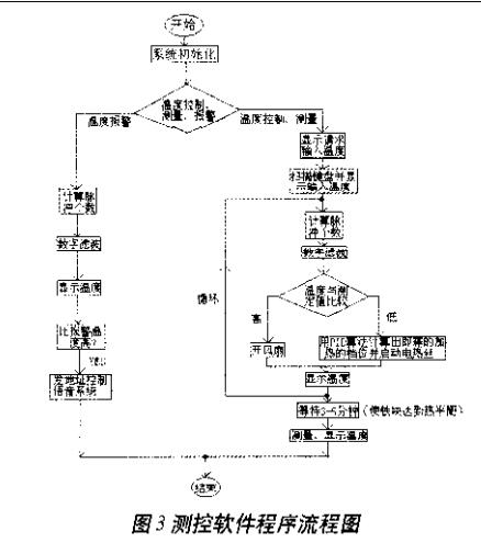
The system uses a PID-like high-precision heating control algorithm and uses a micro-fan to control the overshoot. The program flow chart is shown in Figure 3.
Since the sensitivity of the sensor LM35 is 10 mV/° C., to ensure the control accuracy of 0.1 ° C, the V/F conversion circuit is used to vary the voltage per 10 mV corresponding to a frequency change of 10 Hz. Thus, a temperature change of 0.1 ° C corresponds to a frequency change of 1 Hz, and a resolution of 0.1 ° C is achieved. The frequency is measured by measuring the number of pulses fed, and its stability is very good. A similar discrete PID algorithm is used to infinitely approximate the preset value, achieving high precision control. The principle is to use a resistance wire to heat a simple metal heat balance block for measurement. Therefore, the controlled object can be regarded as an inertial system with a certain self-balancing ability, which can be approximated by a first-order inertia link and a delay link. Its approximate transfer function is:
G(S)=K/[(1+TS)&TImes;(1+Ï„S)]
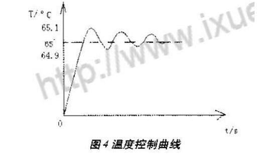
In this system, since T 》 τ, it is only necessary to perform proportional integral adjustment. Finally, the temperature control is converted into the control of the number of warming pulses N, to achieve the goal of temperature control. The general proportional differential integral control algorithm is set by using the method of mass aging or temperature recording (or possibly microcomputer). The system can automatically verify the PID parameter software, and trace and control the curve to verify and check the quality of the control. In order to adapt to the generality of the control system, the system uses the extended response curve method to select the PID parameters. Obtain a temperature control curve with a control target of 65 ° C, see Figure 4.
We are a professional screen protector manufacturer, providing one-stop product production solutions, providing exclusive OEM and ODM services. A wide range of products, including HD Clear Screen Protectors, Self-repair Screen Protectors, Anti-microbial Screen Protectors, Matte Screen Protectors, Privacy Screen Protectors and other series.
We are committed to the development, production and sales of hydrogel screen protectors. We strictly control the screen protector production process to ensure that each product meets industry standards. If you want to know more products, please click the product details to view.
Whether you are a group or an individual, we will do our best to provide you with the best service and the most accurate and comprehensive product information!
Universal Screen Protector, TPU Screen Protector, Hydrogel Protective Film, Mobile Phone Screen Protector, Hydrogel Screen Protector, TPU Protective Film
Shenzhen Jianjiantong Technology Co., Ltd. , https://www.jjtscreenprotector.com