0 Preface
This article refers to the address: http://
Embedded system development has entered the 32-bit era. In the post-PC era where digital information technology and network technology are rapidly developing, embedded systems have penetrated into scientific research, engineering design, and military technology.
Embedded systems usually consist of two major parts, hardware and software. The core components of the hardware are the various embedded microprocessors, and configure the necessary peripherals such as memory, I/O devices, and communication modules. At present, the mainstream 32-bit embedded processors on the market include MOTOROLA, MIPS, ARM and other series. Among them, ARM is the first choice for embedded system design because of its small size, low cost, low power consumption and high performance.
The software part generally consists of an embedded operating system and application software. The embedded operating system is an operating system software that supports embedded applications. It is responsible for all software and hardware resource allocation, scheduling, control coordination and other activities. Since the late 1980s, many typical embedded operating systems have emerged, such as Linux, μC/OS, WindowsCE, etc. The most widely used and popular one is Linux, because its source code is open and available. Good portability and other advantages.
1 embedded video processing platform and Linux system transplantation
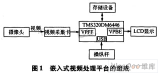
The embedded video processing platform developed in this paper is carried out on the DaVinci digital media technology platform TMS320DM*6. This platform is centered on the embedded processor ARM and consists of necessary auxiliary interfaces such as memory, I/O devices, communication modules, and power supplies. Its workflow is shown in Figure 1. After the camera transmits the video signal, it is converted into a digital signal by the video capture card and then sent to the TMS320DM*6. After processing, it is displayed on the LCD (liquid crystal display) through the video output interface. In this process, it can be connected by the USB port. The joystick is controlled and accessed with the storage device.

This embedded video processing platform is mainly used for video and image processing, such as video tracking, image encoding and decoding, and the like.
This paper elaborates on how to transplant Linux system on TMS320DM*6 platform, and forms a complete Linux transplantation system, which builds a good platform for subsequent development on this platform. The migration process is shown in Figure 2.

2 cross-compilation environment establishment
To develop an embedded Linux system, you must first establish a good cross-compilation environment. The so-called cross-compilation environment is a comprehensive development environment consisting of a compiler, a connector, and an interpreter. Cross-compilation is an important technology in the development process of embedded systems. Its main feature is that the program code executed in a machine is not compiled and generated locally, but compiled by another machine. The former is generally referred to as a tar-get, and the latter is referred to as a host. After compiling the code suitable for the target machine running on the host machine, download the code to the target machine through the debug channel of the host machine to the target machine, and then run the debugging on the target machine by the debugging software control code running on the host machine, and cross-compile it. The development model is shown in Figure 3.

The development tools used to build ARM's cross-compilation environment are: binutils, gcc, glibc. Among them, binutils is a binary file processing tool. It mainly includes some auxiliary development tools, such as obj-dump display reverse sink code, nm list symbol table, readelf display elf file information and segment information. These tools are very useful in the early stages of embedded development, especially when porting debugging operating systems; gcc is a tool for compiling kernel code, can compile assembly language and C language programs, and generate ARM code; glibc is a system call and The C language library for basic functions, which is used by all dynamically linked programs. By downloading these development kits to the host for compilation and installation, you can create an ARM cross-compilation environment.
3BootLoader design
BootLoader is the boot loader, which is a program that runs before the operating system kernel runs. It establishes the environment in which the operating system runs, including initializing hardware, establishing storage space mappings, and passing some basic configuration parameters to the operating system. Therefore, the bootloader is a very important component, it is independent of the operating system, must be designed by the user, and its implementation is highly dependent on the hardware. The relationship between BootLoader, kernel boot parameters, kernel image and root file system image in the space allocation structure of the system storage is shown in Figure 4.

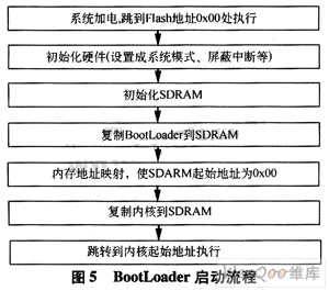
The role of the BootLoader is to properly call the kernel to execute. After the system is powered on, the first instruction executed starts from the 0x00 address of Flash, and the BootLoader program is placed here. Because it is directly operating hardware and has different code according to different hardware environments, it is suitable for writing in assembly language to achieve short and precise execution efficiency; when the kernel is copied from Flash to SDRAM, it is implemented in C language and can realize more complicated functions. Therefore, the design of the BootLoader is divided into two phases. In the first stage of assembly language implementation, the main hardware initialization, set SDRAM, and then copy the Boot-Loader from Flash to the starting address of SDRAM, that is, 2M, the last memory remapping, Flash address mapping from 0x00-0xlff In the 0x1000000-0x11fff, the SDRAM address 0x200000-0xllfff is mapped to 0x00-0xfff, and the control is passed to the loaderkernel() function implemented in C language, and the second stage is entered. The second stage is implemented in C language. It mainly completes the copying of the kernel from Flash to SDRAM, and then the control is given to Kernel. The process is shown in Figure 5. This design code will be very readable and portable.

The first stage design of the BootLoader of this system includes:
a) Close the watchdog program and block all interrupts;
b) set the processor clock and operating frequency, the operating frequency of ARM9 in TMS320-DM*6 is 300 MHz;
c) initializing an external register;
d) initializing the stack pointer;
e) Copy the second stage of the BootLoader to the RAM space and use a jump statement to jump to the C program of the second stage, such as the entry.
The second stage is written in C language. The specific steps are as follows:
a) set the general I / O port parameters;
b) initialize the memory map and memory management unit;
c) initialize the mtd device;
d) copy the Kernel image and the root file system image in Flash to the RAM space;
e) Jump to the first instruction of the kernel. These conditions must be met when jumping: R0=0, R1=machine type ID, R2=start parameter, disable interrupt (IRQ and FIQ), CPU set to protected mode , close the MMU and data cache.
In this way, the BootLoader of this system is designed, and the Linux kernel can be transplanted below.
4 Linux kernel porting
The Linux kernel consists mainly of five subsystems:
a) Process Scheduler: responsible for controlling the use of the CPU by the process.
b) Memory Manager: Standard Linux memory management supports virtual memory, and the total amount of process code, data, and stack can exceed the actual memory size.
c) Virtual File System: hides the specific details of different hardware and provides a unified interface for all devices.
d) Network Interface: Responsible for supporting standard network communication protocols and various network hardware devices.
e) Inter-Process Communication: Supports various communication mechanisms between processes.
According to the characteristics of the embedded system, in order to make the embedded Linux system have certain functions and keep miniaturization, it should include the boot loader, kernel, initialization process, hardware driver, file system, necessary application and so on.
Regardless of which embedded processor, it is necessary to modify all architecture-related code to complete the migration work, mainly referring to kernel population, processor initialization, I/O port mapping, and so on. The specific operations are as follows:
(1) Modify the configuration file
a) Open the Makefile in the root directory, specify the target platform ARCH=arm; specify the cross compiler CROSS_COMPILE=arm-linux-gcc;
b) Open the Makefile in the /arch/arm directory, add the kernel start run address, that is, the location where image.ram should be downloaded. This location is usually offset from the start address of the RAM area by 0x8000.
c) Open the Makefile in the /arch/arm/boot directory and specify the output address of the data after decompression of the bootloader's compressed kernel.
(2) Compile the Linux kernel
After completing the above work, start compiling the Linux kernel and generate the target code. Type the following commands in the kernel source directory:
a) make clean: clear all target files, modules and temporary files generated when the kernel was previously constructed;
b) make dep: search for the dependencies between the Linux output and the source code, and generate a dependency file;
c) make menuconfig: call the menu-style configuration kernel interface, the kernel configuration options are very many, choose a reasonable configuration according to the specific circumstances of their own system, select the corresponding model hardware in the kernel configuration;
d) make zImage: compile the kernel and generate a compressed Linux kernel object code zImage file;
e) make modules: compile block module driver, all selected in menuconfig will be compiled when this command is run.
At this point, the Linux kernel that can run on this system has been compiled.
(3) Create a JFFS2 file system
The file system is an important part of the Linux system. This system uses the mkfs.jffs2 tool to create a JFFS2 file system. First create /bin, /sbin and other directories, then copy the command tool to the /bin folder, copy the system control program to the /sbin directory, copy the library required by the application runtime to /lib, the library file can be from the PC Copy the cross-compiler installation directory. The last key command: mkfs.jffs2-o jffs2root.jffs2, generates the JFFS2 root file system.
After the above work is completed, the BootLoader, Linux kernel, and file system are burned into the Flash of TMS320DM*6, so that the Linux system can be run.
5 device driver development
5.1 Linux device driver development steps
Linux system devices are classified into three types: character devices, block devices, and network devices. The development of its device drivers mainly includes:
a) Define the file_opera-tions structure in the driver source file, and write out the various operation functions required by the device. The operation functions that are not needed by the device are initialized with NULL, and these operation functions will be registered in the kernel.
b) Define an initialization function that will be called during Linux initialization. This function contains: hardware registers to be used to initialize the driver; initialization of device-related parameters; registration of devices; registration of interrupts and functions used by devices; and other initialization tasks.
c) For the use of the driver, you can perform static compilation or dynamic compilation. Static compilation refers to the addition of device drivers to the kernel. Dynamic compilation refers to the compilation of device drivers into driver modules.
This embedded system is mainly used for video processing, and the peripherals involved are mainly display devices and input devices. The display device used here is an LCD, and the input device is connected to the system through a USB interface.
5.2 LCD display driver development
The device driver for the LCD is a driver for the character device and should be written according to the rules of the character device. The Framebuffer technology for LCD display under Linux is a device for extracting graphics and is a good interface for users to enter the graphical interface. The Linux kernel abstracts the Framebuffer device according to the hardware description, and the user-mode process directly writes the screen. You can think of Framebuffer as an image of the display memory. After mapping it to the process address space, you can directly read and write operations, and the write operation immediately reacts to the screen. The device file of the Framebuffer is generally stored in the /dev directory. This device file can be used to display the image.
The LCD display driver mainly includes:
a) LCD driver file structure: including opening device files, device files, other operations, closing device files, etc.;
b) LCD opening: the LCD device is opened in read/write mode;
c) hardware initialization of the LCD device: including registering the LCD device, unloading the LCD device, etc.;
d) setting of the LCD related structure: to obtain the memory start address, the separation rate, the color depth, and the like;
e) mapping the memory area operation: including initializing the memory clearing, etc., reading the image data collected by the camera to the memory to display the image;
f) LCD control output: including getting commands, drawing horizontal lines, drawing vertical lines, drawing circles, etc.;
g) The LCD is turned off.
The above content is implemented by the program and dynamically compiled. After passing, the LCD driver module is transplanted and loaded, and a complete LCD driver is developed.
5.3 USB driver development
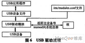
Unlike LCD devices, USB is neither a character device nor a block device, but a new device category. The design framework and flow are as follows: First, provide a ".o" driver module file, and at the beginning Load run. The USB driver will register with the system according to its type. After the registration is successful, the system will feed back a major device number, which is its unique identifier. The USB driver creates a device file placed in the /dev directory based on the major device number. To access this hardware, you can access the corresponding device file with commands such as open, read, and write. The driver will receive the corresponding read or write function and operate according to the corresponding function in the module. The driving process is shown in Figure 6.

The specific design process of the USB driver is as follows:
a) USB driver registration. When the USB driver registers, it sends a command to the function register_chrdev, usually in the driver's initialization function. When the USB device is plugged in, in order to automatically load the driver for the linux-hotplug (hot swappable support for USB devices such as Linux), you need to create MODULE_DEVICE_TABLE. In this process, you need to pass the USB major device number to the corresponding function.
b) The USB device is turned on. Opening the device is done by calling the function open() in the file_operations structure. The main tasks are: check the device related errors, if it is the first time, initialize the hardware device; identify the minor device number; increase the usage count by 1.
c) Release of the USB device. Freeing the device is done by calling the function release() in the file_operations structure. It works just the opposite of open(), which usually does the work: use the count minus 1, and if the usage count is 0, turn off the device.
d) Control information and data read and write of the USB device. The USB device driver can provide an interface for controlling the hardware to the application through functions in the file operation structure, and the read and write operations are also performed by this function.
e) Logout of the USB driver. When uninstalling the driver from the system, you need to log out of the USB device, so you must write a logout function unregister_chrdev.
6 Conclusion
This paper implements Linux porting based on TMS320DM*6 platform, including creating cross-compilation environment, BootLoader design, Linux kernel porting, LCD and USB device driver development, and creating a good embedded platform for real-time video processing application development. Application, GUI and video processing algorithms can be further developed and tested on the platform.
Outdoor Power Supply(700W 1065Wh)
Outdoor power supply, also known as portable energy storage battery, is a device that uses high energy density lithium-ion battery pack as a means of energy storage to provide power supply for users when they are unable to access power. Outdoor power supply can provide power support for almost all electrical equipment. It has larger capacity, supports 220V AC output, USB fast charging output, vehicle cigarette lighter output port, DC output port, lighting flashlight, and even wireless charger and other functions, so as to provide users with more ways of power security as far as possible.
energy storage, power supply, lithium-ion battery, portable lithium battery, DC AC output
Wolong Electric Group Zhejiang Dengta Power Source Co.,Ltd , https://www.wldtbattery.com