Automotive lighting and signal control systems are responsible for automobile lighting and signal lights, as well as control tasks such as electric horns, reversing and brake buzzers. Traditional automotive lighting and signal control systems are controlled by switches, relays, and special electronic oscillators. The control signals are transmitted through special wiring harnesses and do not have self-diagnostic functions. During the driving process of the car, when the important control signals such as the turn signal fail, it is difficult for the driver to detect it, and it is easy to cause a car accident.
1 System hardware platform and working principle
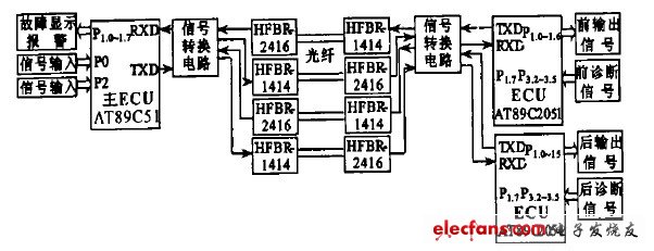
The system consists of a multi-computer system composed of three single-chip microcomputers to realize automobile lighting and signal control. The system's main electronic control unit ECU (Elec2trONic Control Unit) centrally encodes all input control signals and sends them to the front ECU (installed at the front of the car) and the rear ECU (installed at the rear of the car) in a serial manner through optical fiber. ) The parallel output port of the ECU outputs a control signal through a photoelectric isolator, respectively controls the lighting and signaling appliances in the front (rear) of the car, and monitors the lights and signaling appliances in the front (rear) of the car in real time. Once a fault occurs, the front (rear) ECU immediately transmits the fault code back to the main ECU, the main ECU alarms and displays the fault code. The system hardware platform is shown in Figure 1.

Figure 1 System hardware platform
1. 1 ECU
System main ECU adopts AT89C51, front ECU and rear ECU adopt AT89C2051. AT89C51 has built-in 4KB programmable Flash E2PROM, 128 bytes RAM, 2 16-bit timers / counters, 1 serial communication port, 6 interrupt sources, 32 I / O lead, level 3 program memory security, static operating frequency is 24 MHz. AT89C2051 built-in 2KB programmable Flash E2PROM, 128-byte RAM, two 16-bit timer / counter, one on-chip analog comparator, one serial Communication port, 6 interrupt sources, 15 I / O leads, two-level program memory security, static working frequency is 24 MHz.
1. 2 Fiber optic transmitter / receiver
The optical fiber transmitter / receiver adopts HFBR21414 / 2416. HFBR21414 / 2416 emits light at a wavelength of 820 nm, a maximum data transmission rate of 155MBd, a maximum transmission distance of 4 km, and an operating temperature range of-40 ℃ ~ +85 ℃, applicable to 50 / 125μm, 62. 5 / 125μm, 200μm HCS fiber and ST, SC, SMA and FC connectors. The HFBR21414 fiber transmitter contains an aluminum arsenide optical transmitter excited by high-efficiency optical power. The optical transmitter can feed the optical fiber with an optical wavelength of 820 nm (12 dBm) under the excitation of 60 mA DC current. HFBR22416 fiber The receiver consists of a high-efficiency HN photodiode and a low-noise transimpedance preamplifier circuit. The optical signal is converted into an analog electrical signal by the photodiode. After amplification, it is buffered and output by the emitter output device. The maximum dynamic range is 23 dB, and the frequency response From DC to 125 MHz.
1. 3 working principle
The main ECU uses two control words to encode and store all input control signals. The storage format of the two control words is the same, as shown in Figure 2.

Figure 2 Control signal storage format
The main ECU T0 interrupts at a timing of 1.5 ms and generates a square wave signal with a period of 3 ms to control the car horn. Using the T0 interrupt, the soft count is 250 times to generate a periodic square wave signal that causes the turn signal to flash 80 times per minute.
When the input switch signal changes, or the timing time expires, or the soft count times expire, the corresponding bit of the first control word is set, or the bit is inverted. The main ECU timing compares the two control words at 1.5 ms. When the two control words are different, the main ECU sends an update signal through the serial port and updates the second control word with the first control word.
When the front (rear) ECU receives the control signal from the main ECU, it immediately compares it with the existing control signal. If they are different, the output control signal is updated.
1. 4 Self-diagnosis
Front (rear) ECU P1. 7, P3. 2 ~ P3. 5, P3. 7 are the fault monitoring ports, input the self-diagnosis signals of the front and rear lighting and signaling appliances respectively.
Before (after) the ECU sends out a control signal, it will receive a corresponding feedback signal at its fault monitoring port. Comparing the two signals, if they are not the same, it means that the lighting and signaling equipment of the corresponding port has failed, and the front (rear) ECU immediately sends the fault code to the main ECU. After the main ECU receives the fault code, it will alarm and display the fault code.
Power X (Qingdao) Energy Technology Co., Ltd. , https://www.qdpowerxsolar.com