The rapid growth of the valve market puts higher demands on valve control technology. Normally, the valve is manually adjusted, however, in some harsh environmental conditions, manual adjustment is not suitable. In some applications, the control of the valve is not only a simple switch control, but also various relationship control such as opening control and flow. This requires us to design an intelligent automatic valve control system. In view of the simple control and accurate positioning of the stepper motor, it is very suitable for single-chip control. In recent years, techniques for controlling valves using stepper motors have been applied to various fields. To this end, we designed a device that uses the XC866 microcontroller to control the stepper motor to regulate the valve switching angle.
Stepper motor operating characteristics
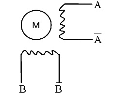
Stepper motors are generally classified into three types: permanent magnet (PM), reactive (VR), and hybrid (HB). Currently, two-phase hybrid stepping motors are the most widely used. This design uses a two-phase four-wire stepper motor with a step angle of 1.8° and no subdivision. The basic principle of the stepping motor is in common with an ordinary permanent magnet synchronous motor, which is an open-loop control element that converts an electrical pulse signal into an angular displacement or a linear displacement. In the case of non-overloading, the speed and stop position of the motor depend only on the frequency of the pulse signal and the number of pulses, and are not affected by the load change, that is, a pulse signal is applied to the motor, and the motor rotates through a step angle. The driving circuit of the stepping motor works according to the control signal generated by the single chip microcomputer. The internal structure of the two-phase stepper motor is shown in Figure 1.

Figure 1 Internal structure of a two-phase stepper motor
As can be seen from Fig. 1, the stepping motor has A and B two-phase windings, due to the particularity of the inductive stepping motor. When a symmetrical positive-rotating alternating current is passed through the two-phase windings of A and B, a circular rotating magnetic field will be generated, and if  The sequence is sequentially applied to the windings to determine the magnitude of the direct current, which will produce a 4-step, one-cycle, step-rotating stator field with a step angle of 90°. In order to make full use of the motor capacity. Increasing the output force distance, the power-on sequence usually used by the two-phase stepping motor in the whole step. At this time, the stepping motor rotates forward, and when the power-on sequence is reversed, the stepping motor reverses.
Design
Here, the control system consisting of Infineon XC866 microcontroller and peripheral chip is used to replace the pulse generator and pulse distributor, and the software is used to control the microcontroller to generate pulses. Design a valve control voltage sampling circuit, use a voltage of 0 ~ 2.5V to control the degree of switching of the valve, the valve is closed at 0V, the valve is fully open at 2.5V. The MCU samples the voltage through the timer interrupt, and after the A/D conversion, it is different from the previous value. If the difference exceeds the allowable fluctuation range, the MCU will determine the steering of the motor according to the positive and negative signs of the difference, and calculate the corresponding number of pulses; then send the pulse to drive the corresponding rotation of the stepper motor, increase or decrease The opening of the small valve. If the difference in voltage is within the allowable fluctuation range, the microcontroller does not send a pulse and the valve is stationary.
1 Introduction to the main control chip XC866
The XC866 single-chip microcomputer is the first product of the 8-bit microcontroller XC800 series introduced by Infineon. It has the advantages of strong processing capability, fast running speed, outstanding safety performance, rich on-chip resources, convenient and convenient engineering development, etc. . Its input/output ports (I/O ports) can be powered by 3.3V or 5.0V; the core requires 2.5V. Key features include a capture/comparison unit (CCU6) for generating pulse width modulated signals with dedicated mode for motor control; features such as automatic sweep and result accumulation (for anti-aliasing or result averaging).
The XC866 integrates a high-performance 8051 core and powerful peripherals. For those familiar with 51 microcontrollers, they can familiarize themselves with their performance in a short period of time and use their rich peripherals to implement a variety of relatively complex applications.
ATS22 is designed for most infrastructure and industrial applications for better in-class protection function and ease of use.
Schneider Inverter Drive,Variable Frequency Drive,High Frequency Converter,Frequency Inverter For Motor
Wuxi Trenty Machinery & Equipment Co., Ltd. , https://www.elec-inverter.com