Research on Sensor Layout of Hunting Trolley Based on Magnetic Field Detection
In the new competition rules of the National University Student “Freescale†smart car competition, the current white wire black road was replaced by a current carrying wire with an alternating current of 20kHz, requiring the car to be controlled by detecting the electromagnetic field signal around the current carrying wire The trolley moves along the current-carrying wire.
Magnetic field model and magnetic field detection
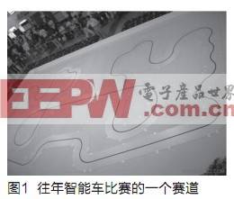
Figure 1 shows the track of the previous year's competition. In 2010, the black line should be replaced by a wire, and an alternating current of 20kHz is passed through the wire. The sensor needs to detect the surrounding electromagnetic field to determine the road (wire) relative to the car. position. It is known from electromagnetics that the space around the wire is filled with alternating electromagnetic fields. If an inductive coil is placed inside, electromagnetic induction will cause alternating current in the coil. Under the condition that the position of the wire and the current in the wire are fixed, the induced current (or voltage) in the coil is a function of the spatial position. Therefore, the inductive coil can be used as a sensor.
Direct analysis of the alternating electromagnetic field is not a desirable method. Considering that the linearity of the problem is much smaller than the electromagnetic wave wavelength of 20 kHz, the DC condition can be discussed first, and then the results can be applied to the alternating conditions. The problem can be simplified as: through the current-carrying wire through the DC current I, it generates a static magnetic field B (x, y, z) in space, the effective value of the voltage U in the inductive coil is proportional to the magnetic induction B (x, y ,z).
In order to obtain the road information from the induced voltage of the inductance coil, it is necessary to analyze the distribution of the magnetic field around the wire. From the Biot-Saffar theorem, the magnetic induction at any point in space can be regarded as the sum of the magnetic fields generated by the current elements on the wire, namely:

The integration path is throughout the current-carrying wire. The above-mentioned integral can only obtain the analytical solution under some specific curves. For the general curve, the numerical solution can be obtained by numerical integration. If you want to investigate the magnetic field distribution in the entire space, you can use some professional electromagnetic field analysis software to complete the analysis. Numerical simulation of space, such as Ansoft Maxwell, CST EM Studio, etc.
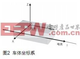
From the perspective of road elements, the track can generally be divided into straight roads, turns, S roads, and loop roads (see Figure 1). The straight road is the simplest. Therefore, the analysis of the sensor response and racing control under the straight road is the basis. . For the convenience of discussion, we make the following conventions: (1) In the car body coordinate system, the direction of the car is defined as the positive direction of the Y axis, the right-hand side along the Y axis is the positive direction of the X axis, and the Z axis points directly above the car , As shown in Figure 2; (2) horizontal coil refers to the inductance coil whose axis is parallel to the Z axis, vertical coil refers to the coil whose axis is parallel to the X axis, and the electromotive force induced by the coil whose axis is parallel to the Y axis is much smaller than the above Two types of coils will not be discussed in this article, but this type of coil will be used in the loop detection; (3) BX is the electromagnetic induction strength pointing to the right-hand side of the current-carrying wire, and BZ is pointing to the current-carrying guide The electromagnetic induction intensity directly above. Obviously, the vertical coil induces the BX change rate, and the horizontal coil induces the BZ change rate.
The magnetic field distribution near the straight track can be approximated to the magnetic field distribution on an infinitely long straight wire, and it is easy to calculate the magnetic induction intensity at a point r away from the long straight wire:

Then it can be launched:
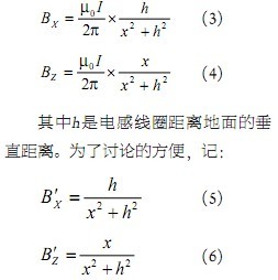
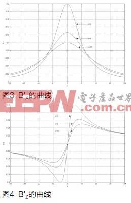
Then B'X and B'Z have the same trend as BX and BZ respectively. Figures 3 and 4 show the change trend of B'X and B'Z when taking 5, 8, and 10 respectively. It can be seen from the figure: (1) B'X is an even function of x, monotonous on both sides of the Y axis; B'Z is an odd function of x, there is no monotonic relationship on both sides of the Y axis; (2) At the same height, B'X amplitude is twice that of B'Z, but at x = 20, B'X is only about half of B'Z, so B'X decay much faster than B'Z. In summary, it can be inferred that the horizontal coil is more suitable for determining the positive and negative of x, and the vertical coil is more suitable for solving the specific value of x. B'Z decay is much slower than B'X, indicating that the horizontal coil is relatively It is more sensitive and can be used to predict the curve ahead.
Position solving algorithm
The location solution is to determine the current road type and location through the sensor detection value. The position of the road is usually described in the car coordinate system. As shown in Figure 5, ABCD stands for the car body, and XY is the car body coordinate system. If the sensor is placed on the four corners, the position resolution is through the induction of the coils on the four corners The voltage determines the coordinates of the intersection points E and F of the current-carrying wire with AB and CD, and infers the shape of the road (current-carrying wire).
Position calculation based on double vertical coils
The changing characteristics of the induced electromotive force in the vertical coil make it suitable for solving specific position parameters. B'X is an even function, and the value of a coil cannot be determined whether it is positive or negative (left or right of the wire), so consider placing one on each side symmetrically, as shown in Figure 5 A and B.
Consider the straight line first. Remember that the length of AE is lA, and the length of BE is lB, which is easily obtained from equations (5) and (6) and knowledge of electromagnetics. The effective values ​​of the induced voltages in the vertical coils of A and B are:
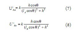
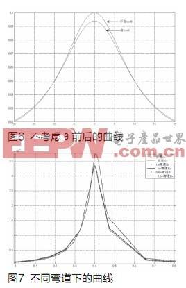
Where k is a proportional constant, related to the electromagnetic environment and the specific electromagnetic coil, which can be determined by experiment, and q is the angle between the wire and the Y axis of the car coordinate system, as shown in Figure 5. Obviously, using equations (7) and (8) to solve lA and lB is not a simple matter, it is best to remove cosq. Figure 6 shows the curves of U'Ax before and after cosq when q = 20o, h = 10, k = 1. At this time, the declination angle q has a certain effect only when the value of lA is small. At the same time, when q is smaller, this effect will be more limited. Therefore, in the approximate analysis, cosq can be removed. For the convenience of analysis, the equations (7) and (8) are simplified to:
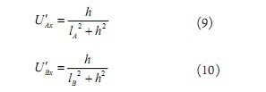
U'Ax, U'Bx are physically the effective values ​​of the vertical sensor induced voltages at points A and B, respectively, divided by the proportional constant k in equations (7) and (8), so they are known data in the solution algorithm . Solving lA and lB from equations (9) and (10) is relatively simple. Two algorithms are given below:
(1) Since the distance between the two sensors is fixed and known, you can set
![]()
The above formula and (9) (10) are combined to solve:
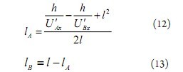
Note that it is meaningful to take negative values ​​of lB and lA, indicating that the wire is out of line segment AB.
(2) Note that at that time, A must be on the left side of the current-carrying wire; at that time, A and B were arranged on both sides of the current-carrying wire; at that time, B must be on the right side of the current-carrying wire. therefore:
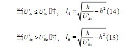
The other two quantities can be solved by equation (11).
When the road is not a straight line, because the induced voltage in the vertical coil decays faster on both sides of the wire, the shape of the current-carrying wire at a distance has little effect on it. Figure 7 is the curve of BX for straight, 1m radius and 0.5m radius curves obtained by numerical simulation when h = 0.1m. It can be seen that the effect of radius on BX is basically negligible, so the above derivation can still be approximated Established.
In summary, by placing two vertical coils side by side, the position of the intersection of the current-carrying wire and the two vertical coils in the cart coordinate system can be determined.
Road estimation based on mixed layout
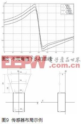
The change in road shape does not have much impact on BX, but what about the impact on BZ? Figure 8 shows that when h = 0.1m, the radius of 1m and 0.5m on a straight road obtained by finite element numerical simulation The curve of BZ with x on the curve (where 0.4 to the left is the inside of the curve). It can be seen from the figure that the radius of the curve has a nearly linear effect on the BZ on the inside of the curve that is not too close to the wire, and this effect hardly changes in the corresponding area (the interval 0 ~ 0.35 in the figure). Therefore, consider installing a horizontal coil beside the symmetrically installed vertical coils at the same time to form a hybrid arrangement of detection methods, such as at points A and B.
Suppose the effective value of the actual induced electromotive force of the two-point horizontal coil A at a certain position is U'AZ. In addition, according to formula (4), it can be deduced that at this position, the effective value of the induced electromotive force U'AZ excited by the corresponding long straight current-carrying wire is:

k is a proportional constant, which can be determined by experiment, and q is the angle between the road (long straight line) and the Y axis of the car body coordinate system. Similarly, it can be ignored in the approximate estimation. make:
![]()
Then, when DUA> 0, point A is on the inside of the curve, when DUA <0, A is on the outer measurement of the curve. In practical applications, considering the detection error, the right side of the inequality sign should be a constant greater than 0, you can Choose according to the situation. According to Figure 8, there are also the following formulas for estimating the radius of a curve:
![]()
Among them, a should be determined according to experiments, and different values ​​should be determined in different intervals of DUA.
Some principles and examples of sensor layout
From the above analysis, some principles of sensor coil arrangement can be obtained. The combination of two vertical coils and two horizontal coils can independently obtain relatively rich information, so they can be used as a sensor group in the application. As can be seen from Figure 3, the coil height h should be appropriate, h is too small, the magnetic field strength wire is concentrated near the X-axis origin, wasting the measurement range of the sensor, and is not conducive to the measurement of the distal end of the X axis; too large, the magnetic field strength is too small It is not easy to measure, and the curve changes gently, which is not conducive to improving the resolution of distance measurement. Figure 8 also shows | x |
Fig. 9 is an example of the arrangement of the sensor coils. The position parameters are as shown in the figure. The height is uniformly arranged on the 8cm horizontal plane. 5 sets of 4 × 20 inductance coils are used, divided into four rows, three rows in front of the car, The last row. The distance between the sensors in the front of the car is extended row by row, and the front row is extended to 24cm. In order to improve its detection accuracy, two sensor groups are used. The direct detection distance is 20cm in front of the car, and the predicted distance of the frontmost coil is 10 ~ 30cm, so the layout scheme can perceive the route of 30 ~ 50cm in front of the car, plus the length of the body is about 20cm, so a total of roads in the range of 50 ~ 70cm before and after the car Information, can basically meet the control requirements of racing cars running at 3 ~ 5m / s.
Electrolyte Lithium Hexafluorophosphate (LiPF6)CAS:21324-40-3
Shandong Huachuang Times Optoelectronics Technology Co., Ltd. , https://www.dadncell.com