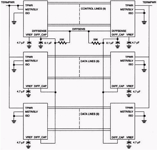
OverviewIn a typical applicaTIon the SCSI devices are daisy-chained as shown in Figure 1. The DIFFCAP signal monitors the DIFFSENS line to determine the proper operaTIng mode of the device. The DIFFSENSE pin can also drive the SCSI DIFFSENS line (when MSTR / SLV = 1) to determine the SCSI bus operaTIng mode. The DS2117M, DS2118M, DS2119M, and the DS2120 each respond appropriately according to the device funcTIonality. Since the DS2120 is a low-voltage differential (LVD) -only device, it isolates the termination pins from the bus in both single-ended (SE) and high-voltage differential (HVD) mode operation. The DS2117M, DS2118M, and DS2119M are SE / LVD multimode devices and isolate the SCSI bus only in HVD mode.

Figure 1. SCSI bus typical configuration.
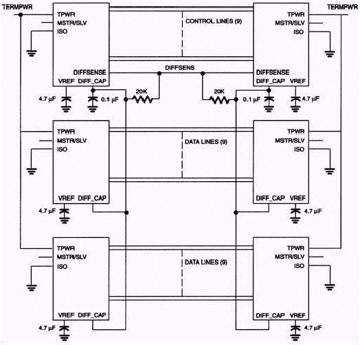
Alternate ConfigurationInternal to these devices, there is a 75kΩ internal pullup between the TPWR and the MSTR / SLV lines. Figure 2A illustrates the existing internal pullup not shown in Figure 1 and not shown in the data sheets for the multimode and LVD-only devices. Because of the internal pullup, the MSTR / SLV line can be connected high, as shown in Figure 1, or it can be left floating, as shown in Figure 2A. Typically, users would connect the MSTR / SLV line high but this is optional and not a requirement.

Figure 2A. SCSI bus alternate configuration.

Figure 2B. SCSI bus alternate configuration.
From Figure 1, you see that only the device designated as the master is connected high (MSTR / SLV = 1). Only the master device is configured to drive the DIFFSENS line. Slave devices monitor the DIFFSENS line though DIFFCAP pin. In the typical configuration, the MSTR / SLV line is connected low for all slave devices. However, by leaving the MSTR / SLV line floating, as shown in Figure 2A, the effect is negligible because none of the slave devices drive the DIFFSENS line and therefore do not control the mode selection.
SummaryBecause of the internal pullup between the termpower voltage (TPWR) and the MSTR / SLV, the DS2117M, DS2118M, DS2119M, and the DS2120 devices can be configured as shown in Figure 1 or optionally as shown in Figure 2A without any difference in SCSI device operation.

Figure 1. SCSI bus typical configuration.
Alternate ConfigurationInternal to these devices, there is a 75kΩ internal pullup between the TPWR and the MSTR / SLV lines. Figure 2A illustrates the existing internal pullup not shown in Figure 1 and not shown in the data sheets for the multimode and LVD-only devices. Because of the internal pullup, the MSTR / SLV line can be connected high, as shown in Figure 1, or it can be left floating, as shown in Figure 2A. Typically, users would connect the MSTR / SLV line high but this is optional and not a requirement.

Figure 2A. SCSI bus alternate configuration.

Figure 2B. SCSI bus alternate configuration.
From Figure 1, you see that only the device designated as the master is connected high (MSTR / SLV = 1). Only the master device is configured to drive the DIFFSENS line. Slave devices monitor the DIFFSENS line though DIFFCAP pin. In the typical configuration, the MSTR / SLV line is connected low for all slave devices. However, by leaving the MSTR / SLV line floating, as shown in Figure 2A, the effect is negligible because none of the slave devices drive the DIFFSENS line and therefore do not control the mode selection.
SummaryBecause of the internal pullup between the termpower voltage (TPWR) and the MSTR / SLV, the DS2117M, DS2118M, DS2119M, and the DS2120 devices can be configured as shown in Figure 1 or optionally as shown in Figure 2A without any difference in SCSI device operation.
Nantong Boxin Electronic Technology Co., Ltd. , https://www.bosencontrols.com