From personal computers to flat-panel TVs, any consumer product with a power supply has a small fan on the back for circuit cooling. The use of thermistors instead of thermocouples has become more popular when it comes to controlling fans.
The use of thermistors to control temperature is nothing new. Since the 1970s, the device has been used to measure the rise and fall of PCB heatsink temperatures. This article will explore its operation and performance in fan control to reduce noise and increase efficiency.
In the thermistor-based fan control, if the ambient temperature rises above room temperature, the temperature measuring bridge will detect the rise in temperature and turn on the fan. This work is fully automated and the fan will turn off when the ambient temperature returns to room temperature.
A negative temperature coefficient (NTC) thermistor is very effective in detecting an increase in ambient temperature. Because of the negative temperature coefficient, the resistance of the thermistor will decrease as the ambient temperature rises. The temperature measuring bridge in this example utilizes this unique feature of the thermistor in controlling the operation of the fan.
Temperature measurement application
The fan in the circuit enhances energy efficiency and reduces the noise effect generated by the fan by properly cooling the circuit. Electrical noise is usually caused by the failure of the fan to operate at full power.
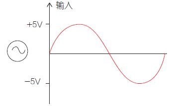
   Figure 1: Input signal in the comparator circuit.
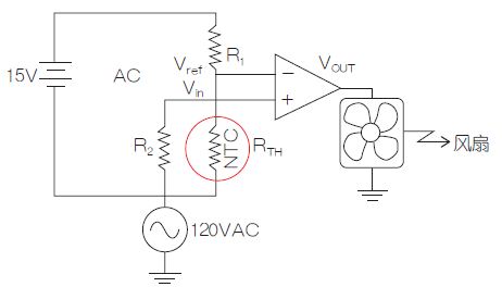
   Figure 2: Temperature measurement bridge circuit.
Figure 2 shows a typical temperature-measuring bridge circuit for fan control. The resistor R2 (50W, 300Ω) is determined by the following equation, which will affect the input signal.

The input signal of Figure 1 is applied to the comparator circuit of Figure 2.
Reference voltage calculation at 70 ° C and 50 ° C
According to customer needs, the application will work when the ambient temperature reaches 70 ° C or 50 ° C (ie the fan will turn on).
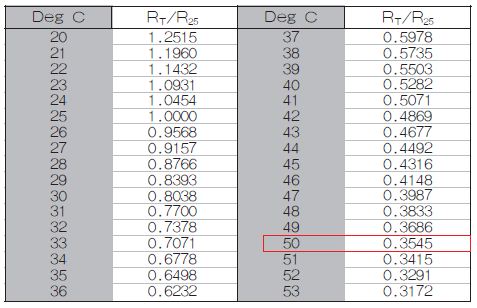
Assuming RTH is 10,000 Ω at 25 ° C or room temperature, then at 70 ° C, the RTH is 1,470 Ω.

The value in the formula (1) is calculated from the thermistor RT characteristics shown in Table 1.
Table 1: Ideal values ​​for thermistor RT characteristics at 70 ° C or 50 ° C.
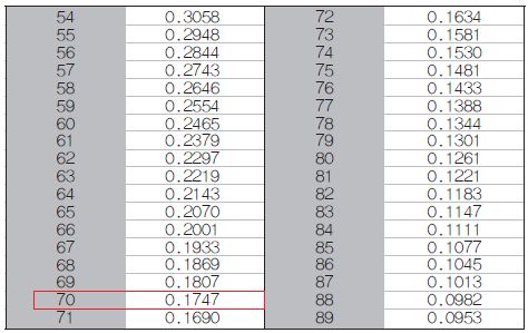
Therefore, the reference voltage at 70 °C is calculated as follows:
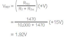
Similarly, the RTH at 50 ° C is 10,000 × 0.3545 ≈ 3545 Ω.

The value in the formula (2) is calculated from the thermistor RT characteristics shown in Table 1.
Therefore, the reference voltage at 50 °C is calculated as follows:

Fan on condition
When the input voltage exceeds the reference voltage, the fan will turn on, but this condition depends on the ambient temperature. Note: The resistance of the thermistor depends on the ambient temperature.
At 70 ° C, if the input voltage exceeds 1. 9 2V, the output voltage will switch to +12V level; when the input voltage is lower than 1.92V, the output voltage will switch back to -12V level.
At 50 ° C, if the input voltage exceeds 3. 9 2V, the output voltage will switch to +12V level; when the input voltage is lower than 3.92V, the output voltage will switch back to -12V level.
What happens at room temperature?
The reference voltage at room temperature (25 ° C) is:

Because the maximum input voltage is ±5, it will never exceed +7.50V, so the fan will remain "off".
Ametherm's PANE103395 is perfect for this application. This small thermistor reacts quickly to rising ambient temperatures. Its 5% accuracy reduces any deviations in performance.
Pv Connector,Mc4 Connector,Solar Panel Connectors,Solar Connector
Sowell Electric CO., LTD. , https://www.sowellsolar.com